
The LAAS Clubhouse Project Renderings
Select an image below to display that image at full size.
Select your browser's Back < button to return to this page after viewing an image at full size.

Entry to east
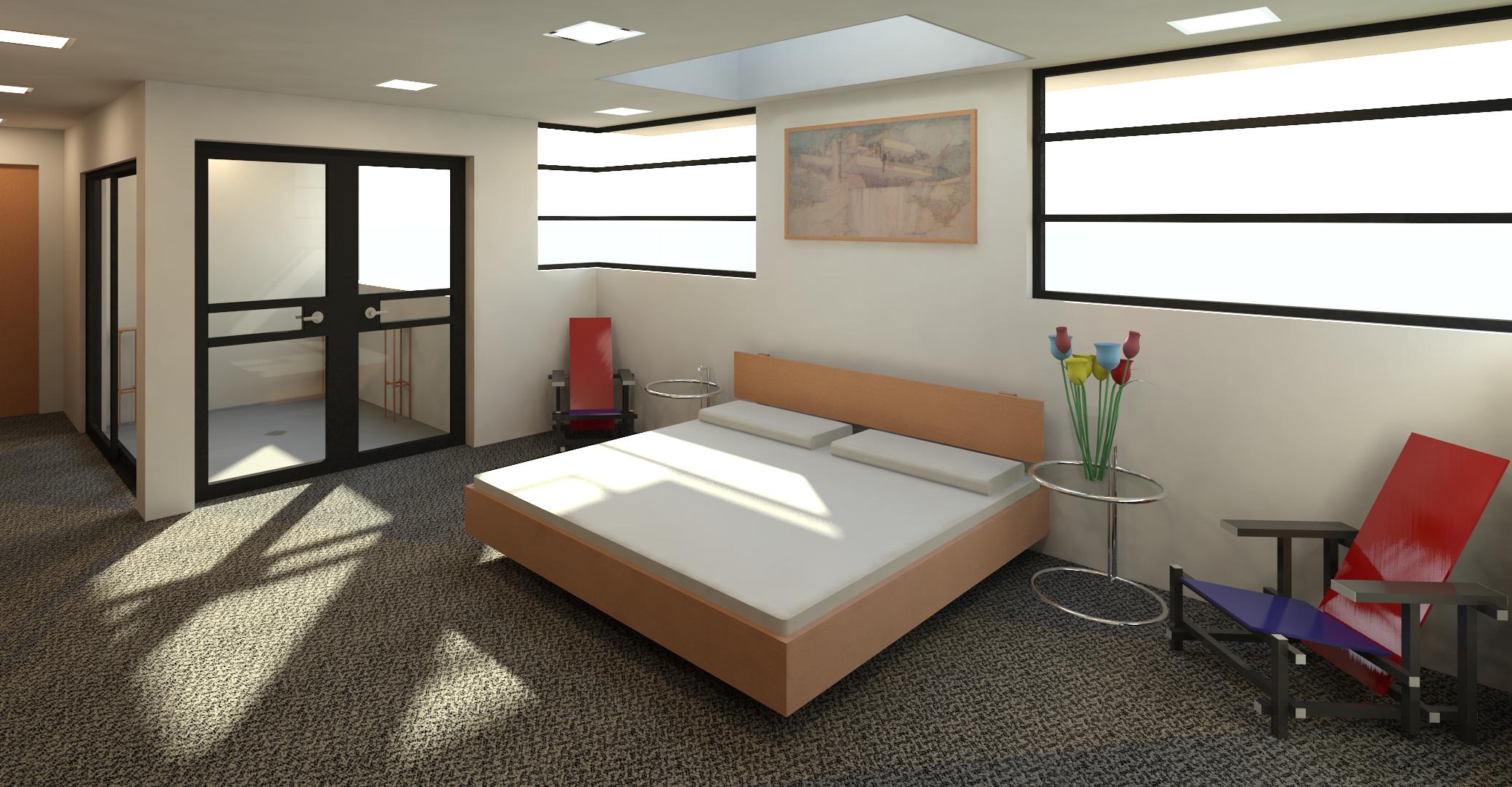
In this version, the wall panels have been raised near the bottom of the glazing panels. However, in subsequent versions, the wall heights will be limited to no more than 10' - 0" high. The walls for the bathroom areas don't need to extend as high as currently depicted.
 Bathrooms to entry
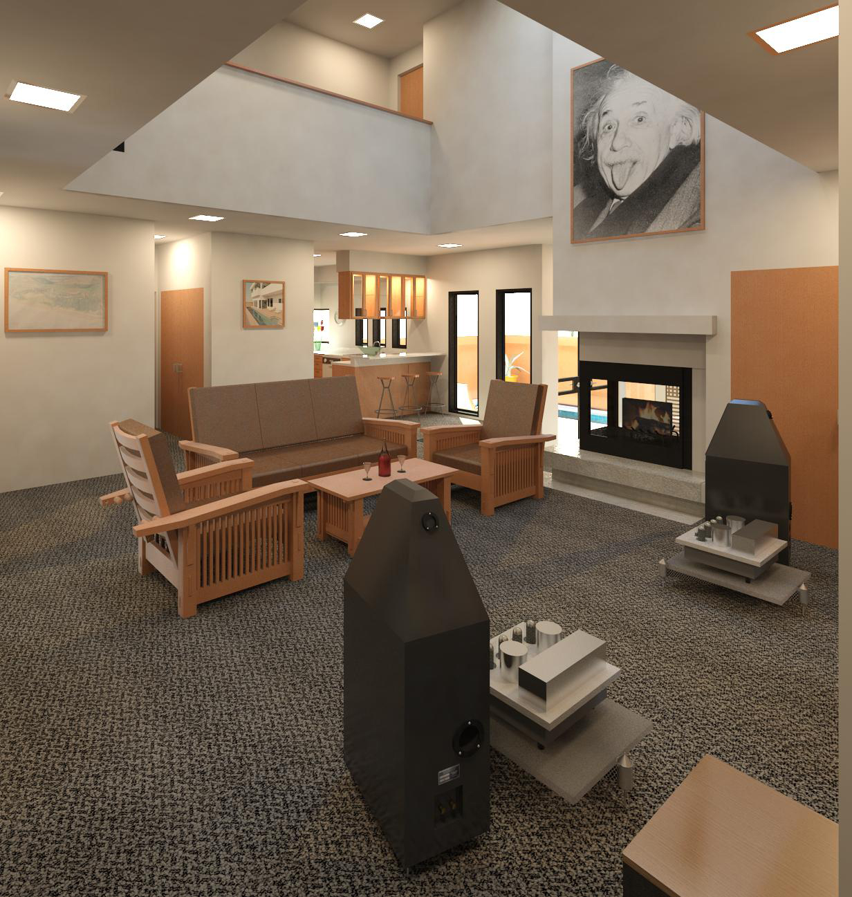
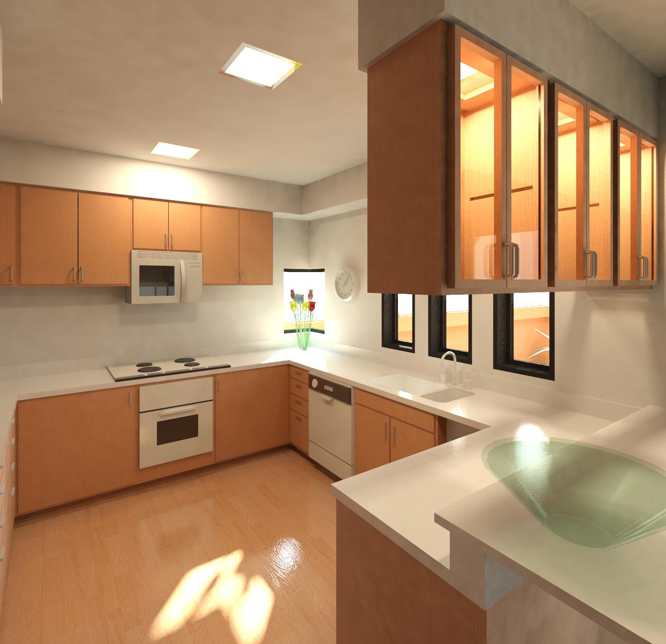
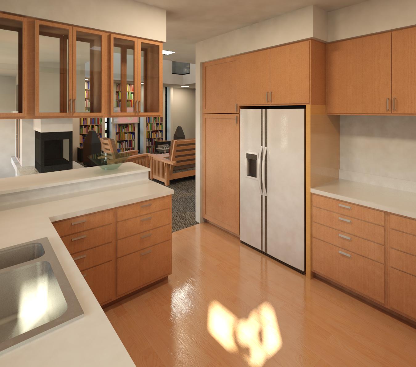
The appliances in the kitchen wall to the south west in this view are (left to right) double wall ovens, a refrigerator, and a microwave oven. The rest of the wall space is cabinetry. A double-basin sink and an induction cook top are modeled on the counter top. A trash compactor is visible in the kitchen island. A dishwasher is on the north side of the island opposite the sink.

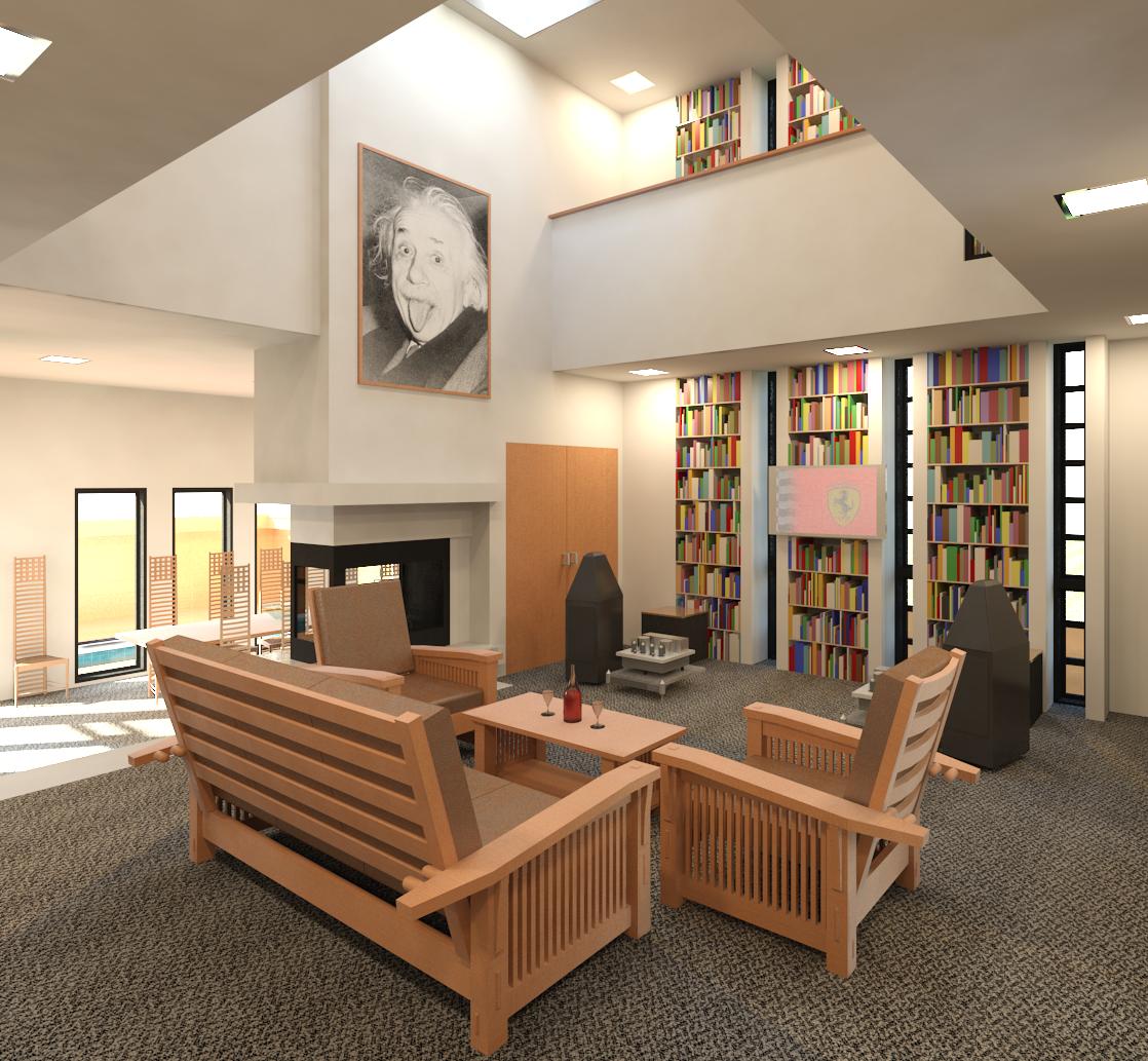
 View to north
The primary entry door to the left within this view needs to be addressed so that the door and frame are incorporated into the roof dome structure.
 View to south
The secondary entry door to the left in this view needs to be addressed so that the door and frame are incorporated into the roof dome structure.
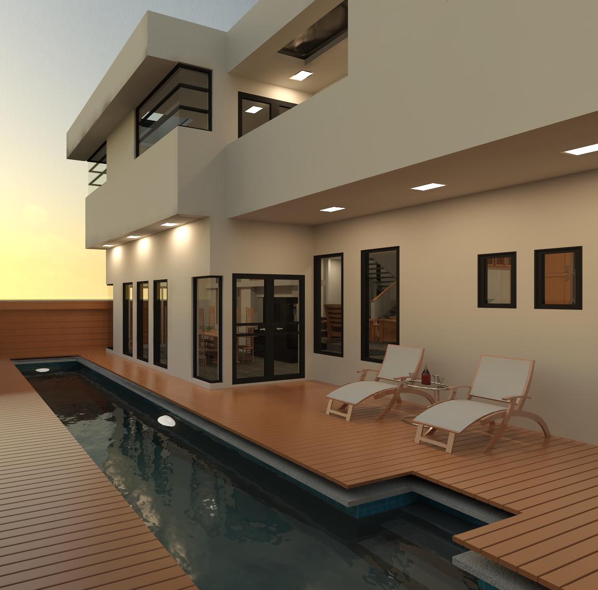
 View to west
The secondary entry door to the right in this view needs to be addressed so that the door and frame are incorporated into the roof dome structure.
 First floor: kitchen to the north-west
This earlier version depicts the kitchen before the sinks were lowered and the material changed to represent white Corian.
 Aerial view to the north
The secondary entry door in the upper-right as well as the primary entrance door to the left in this view needs to be addressed so that the door and frame are incorporated into the roof dome structure.
 Aerial view to the south
The secondary entry door in the lower-left as well as the primary entrance door to the right in this view needs to be addressed so that the door and frame are incorporated into the roof dome structure.
 Aerial view to the east
An enclosure for the secondary door at the left of the dome and the primary entrance at the bottom in this view needs to be designed and modeled so that the door and frame are incorporated into the roof dome structure.
 Aerial view to the west
An enclosure for the secondary door at the lower right of the dome in this view needs to be designed and modeled so that the door and frame are incorporated into the roof dome structure.
 Floor plan
North is up. The grid lines define a triangular pattern dictating how the various walls and furniture components are oriented.
The Los Angeles Astronomical Society Lockwood Valley Club House project version 02 overview
The Los Angeles Astronomical Society (LAAS) Club House project started in September 2011 while attending the Pacific Astronomy and Telescope Show (P.A.T.S.) in Pasadena when Dr. Tim Thompson and I talked about what was going on at the LAAS' Steve Kufeld astronomical observing site in Lockwood Valley CA. Actually, Tim did most of the talking which turned out to be a useful thing for him to do. Tim mentioned that the LAAS needed to remove an old trailer home that was set up on the site in the 1980s that was being used as a "warming hut" of sorts where members could get out of the cold evening or early morning air and warm up a bit before continuing to observe the sky during the Star Parties held at the site. Tim mentioned that he was considering having the LAAS replace the old dilapidated trailer with a single small shipping container modified to include a toilet and sink. That remark sparked the idea for this project. I had the basic layout decided upon before our conversation was over although I did have to modify the placement of objects within the structure to accommodate the grid system.
The structure is comprised of a circular 0' - 6" thick perimeter wall of poured in place concrete 3' - 0" high resting upon a foundation footing. The wall measures 48' - 0" across from the centerline of the perimeter wall to the centerline of the wall on the opposite side. On top of the perimeter wall sits a curtain wall system comprised of roughly 3' - 1" x 3' - 0" glazing panels held in place with a radial mullion system forming a dome shape. The top of the dome is roughly 19' 0" high. The design of the dome will change as various glazing schemes are experimented with.
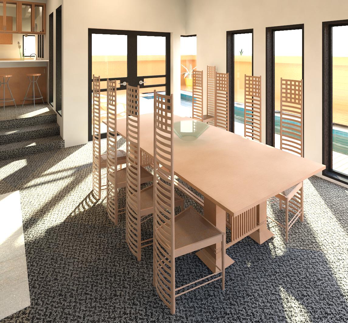
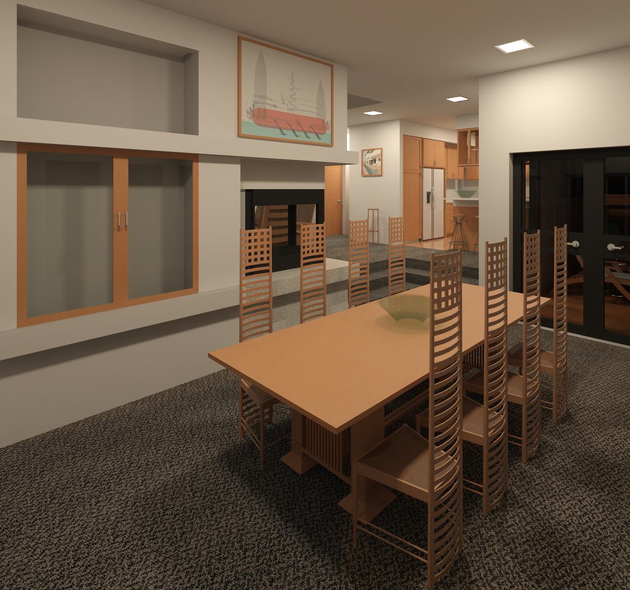
The interior spaces are defined by the use of a 4' - 0" triangular grid system imposed upon a poured in place concrete floor. One goal of the design was to enable the LAAS to convert the Club House structure into a useable cabin dwelling should they decide to sell the site at a future date. Therefore, the layout of the internal spaces fairly mimics that of a dwelling including a sitting area (Living Room), a kitchen, dining area, and two large ADA-compliant bathrooms (one for three males and the other for three females). The toilets and the urinals are wall-hung to facilitate cleaning the bathroom floors. The large bathrooms could be converted into two bedrooms with a single bathroom. The central seating bench could be replaced with a fireplace mass. There is a main entrance with a concrete and wood deck and a smaller secondary emergency exit with a small concrete deck.
CDX Plywood from CDF-Certified environmentally friendly managed forests was chosen as the primary material for the custom seating benches, cabinetry, dining table, and wall surfaces. Foam-filled cushions are modeled for the bottom and backs of the seating benches. The counter top material finish is depicted as a solid white man-made material such as Corian. The plywood will be cut on a CNC router table based upon the modeled designs.
To reduce the amount of light that is emitted through the glazing (specifically along the south perimeter toward the telescope observing pads), the interior of the glazing panels can be painted to render them opaque. A lighting plan will be modeled as time permits then a number of night renderings can be generated.
The structure is intended to make use of a whole house heat recovery ventilation system, an air source heat pump, and the concrete floor could be heated with a radiant heating system. If the budget allows, a couple of vertical wind turbines along with a series of photovoltaic panels can be added to reduce energy costs.
Note that a dome comprised of a radial rib system as currently modeled is not the most practical design. A geodesic dome may be a lower-cost choice that is easier to construct by non-professional builders (LAAS members). Raising the height of the perimeter wall may also be beneficial. Therefore, I shall create other design variations as time permits but this initial design has been a fun exercise and it is my first attempt at generating a dome using the Revit application.