
The John Lautner's Harpel Residence Renderings
Select an image below to display that image at full size.
Select your browser's Back < button to return to this page after viewing an image at full size.
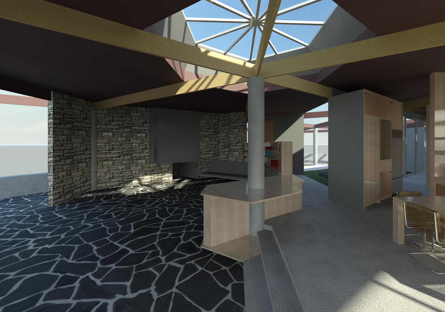
Dining room to loggia
The height of the columns and the roof are probably higher than specified, but without access to the elevations in the original plans, only a guess will suffice. The beams and roof will be lowered if required whenever access to the elevations or accurate measurements at the site are permitted.
White oak with a light clear finish is the wood species and finish currently depicted for the cabinetry. This will be changed once the actual species and finish used is identified. The beams in the interior appeared to be stained almost black or soaked in creosote. This will have to be verified and the finish of the beams in the model altered as required.
The flooring in the living room and the patio surrounding the swimming pool consists of random-cut black slate and white mortar.
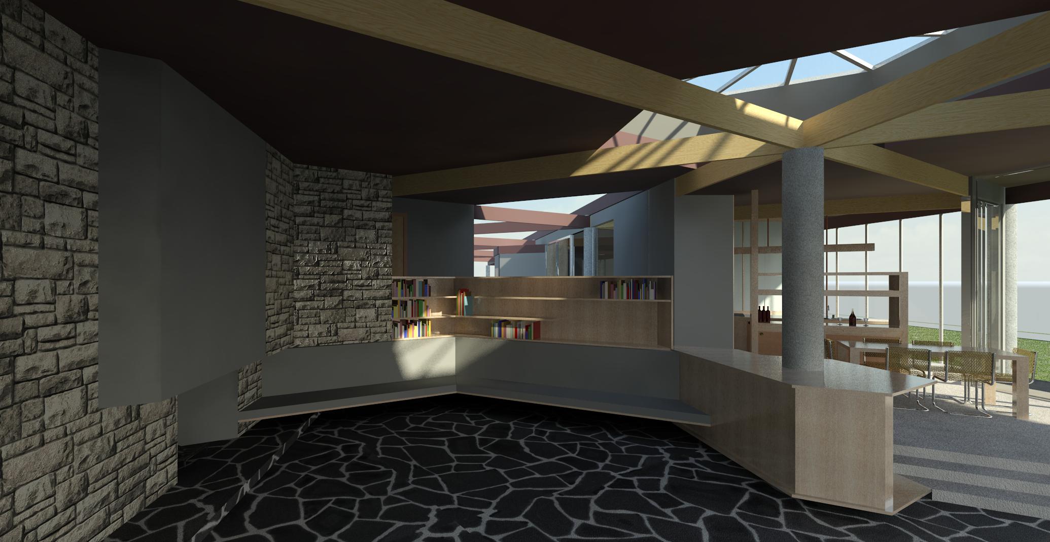
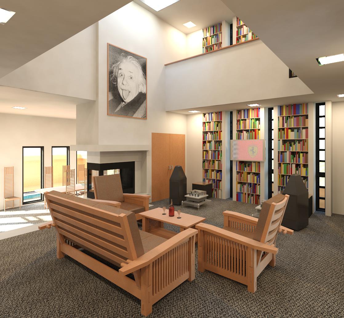
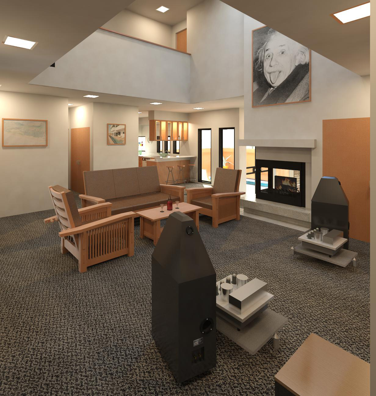
Living room to W
The type and layout of the stone depicted on the walls is not correct. What is currently depicted is a stone material image provided with the 2012 version of the Revit ® Architecture application. A more appropriate custom off-white stone around the fireplace will be modeled as time permits.
The roof structure will be altered to reflect the actual method of construction which appears to be 2" x 6" rafters over the beams covered by tongue and groove planking, which in turn is covered in insulation and finally by a white waterproof membrane.
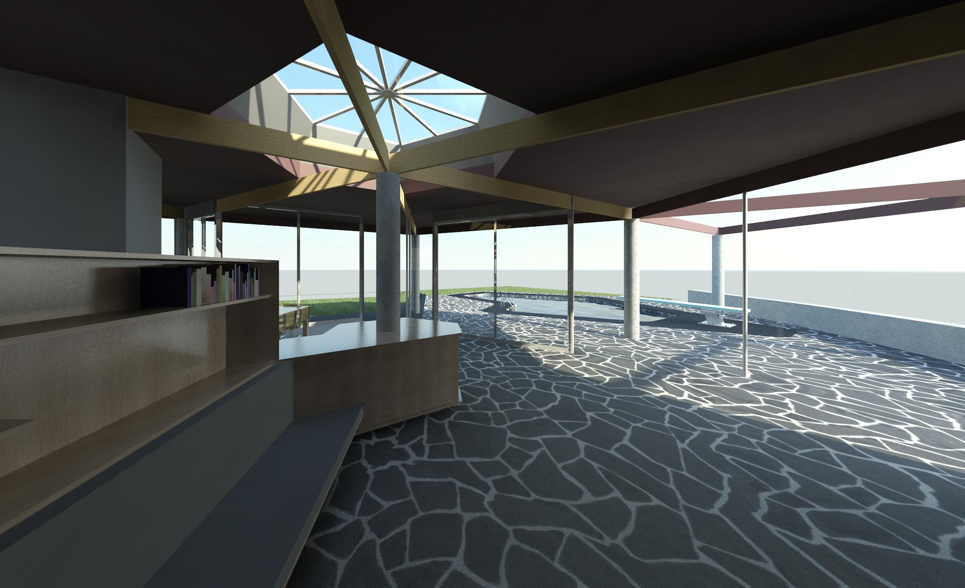
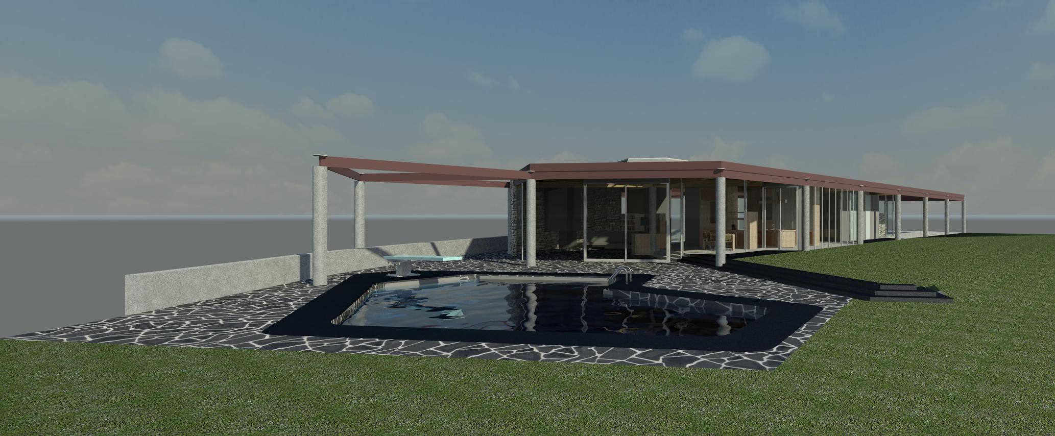
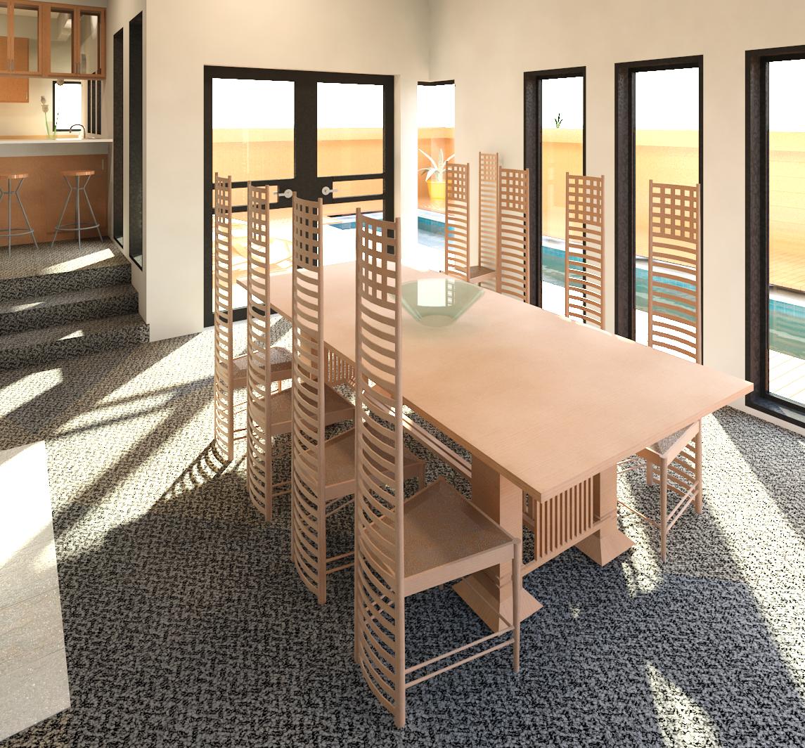
 Dining room to swimming pool E
The table top surrounding the concrete column is notched along the North face, but the table top was not notched when we toured the house. The model reflects the original floor plan.
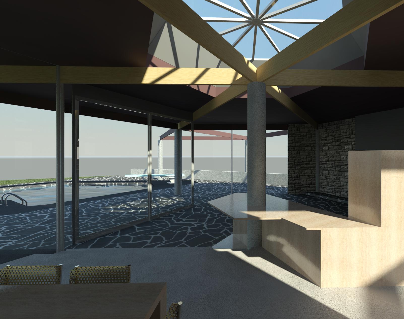
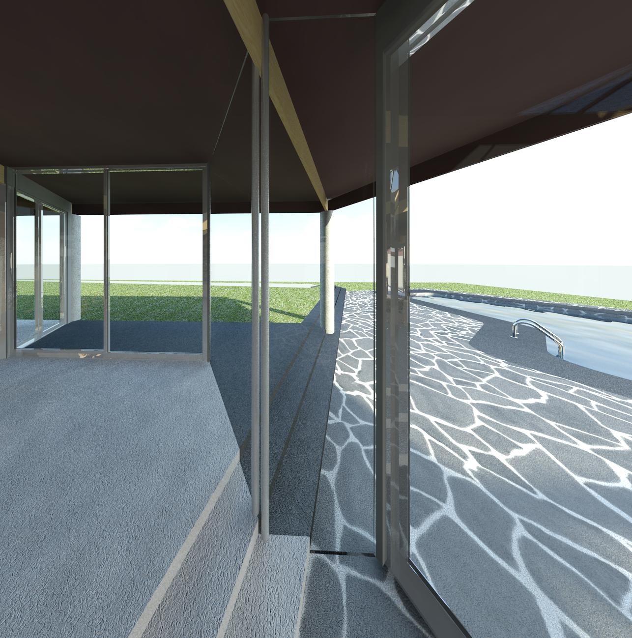
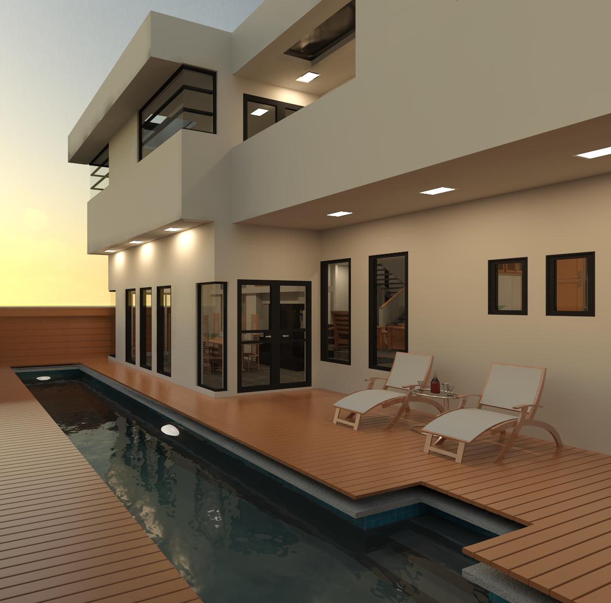
 Living Room to Pool E
The back of the seating bench and cushion should be set at an angle for comfort, but without access to the correct angle specified in the original plans, they are currently depicted as being vertical.
 Dining room to N
The exterior concrete on the North side of the house and the swimming pool coping are tinted black.
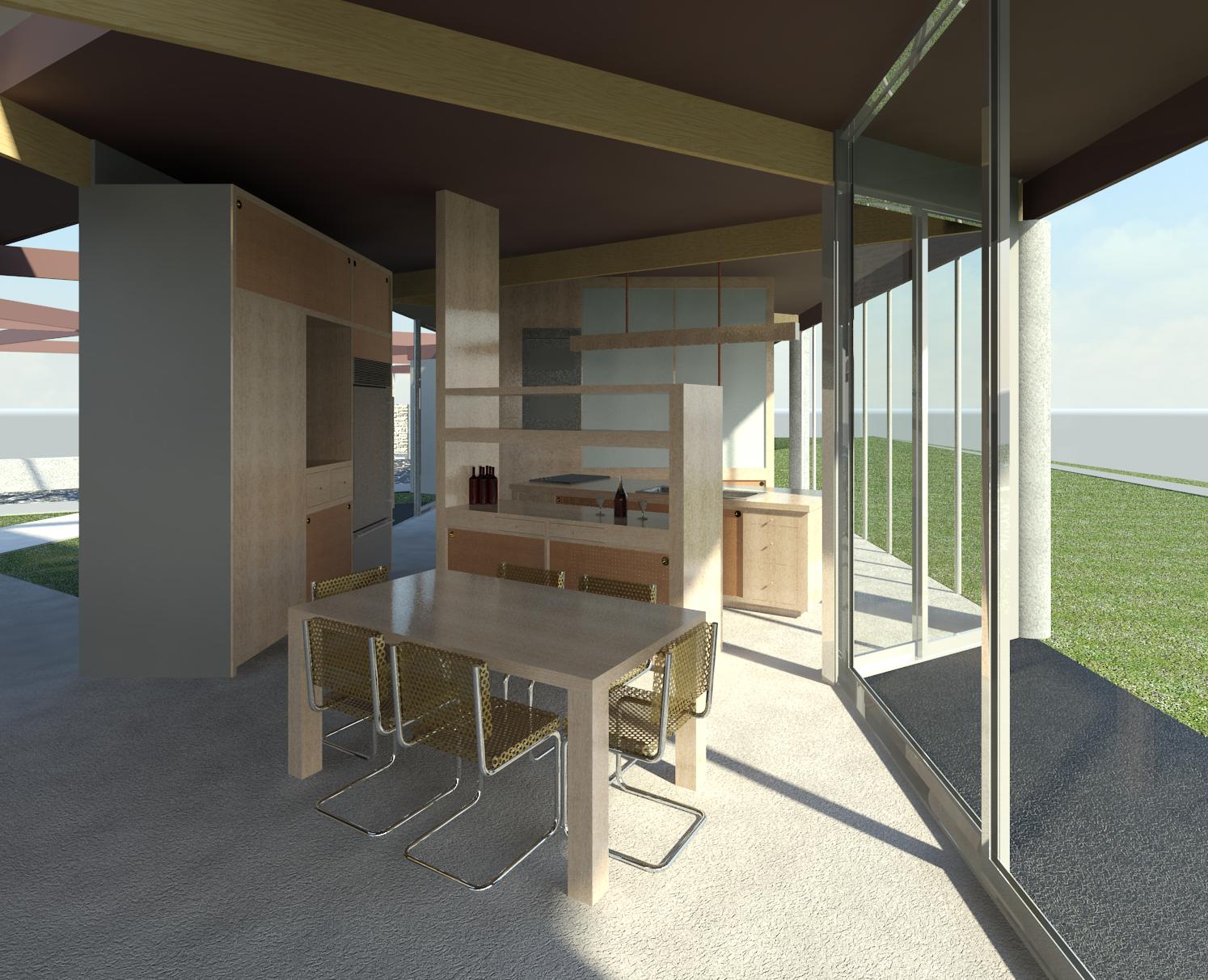
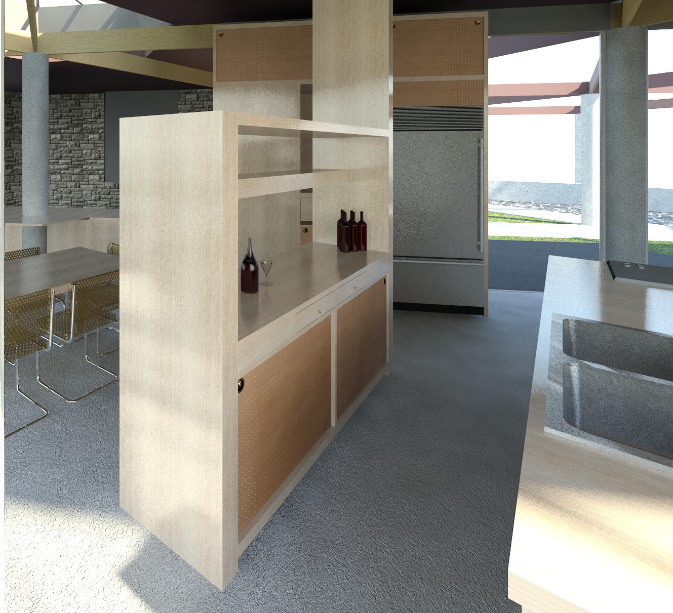
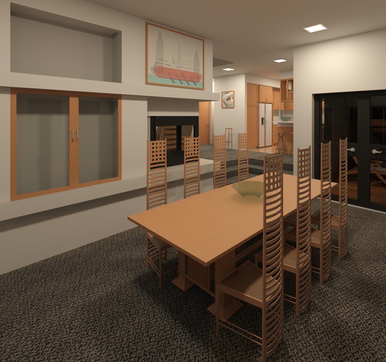
Dining room to kitchen W
The oddly-shaped structure with the bottles of wine and two glasses between the kitchen island and the dinning room table is a bar. A period photo depicts the South (left in this view) end of the bar continuing higher than the North (right in this view) side of the bar. Not knowing how high the South end extended, the South end of the bar continues to the roof structure. The void in the South wall may have been used to house conduits for lighting and electrical outlets in the bar.
The exterior concrete on the North side of the house is tinted black.
Contemporary kitchen appliances are depicted until such time as suitable images of period appliances are found to model.
 Bar to kitchen NW
The drawers and sliding pegboard doors in the kitchen island and bar are placeholders until the cabinetry elevation drawings can be accessed. Correctly-sized drawers and doors will be modeled when the cabinetry details are made available.
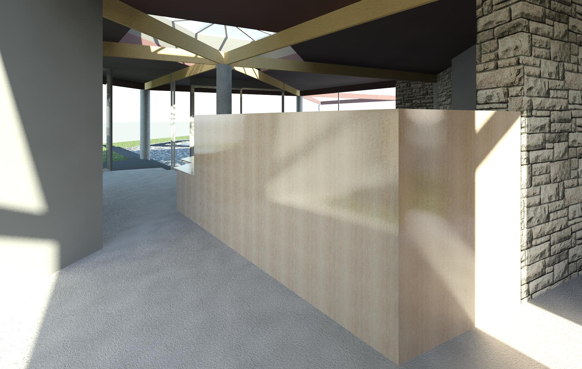
 Bar to entry
The dimensions of the drawers and pegboard sliding doors are just placeholders until access to the elevation drawings depicting what was actually intended is granted.
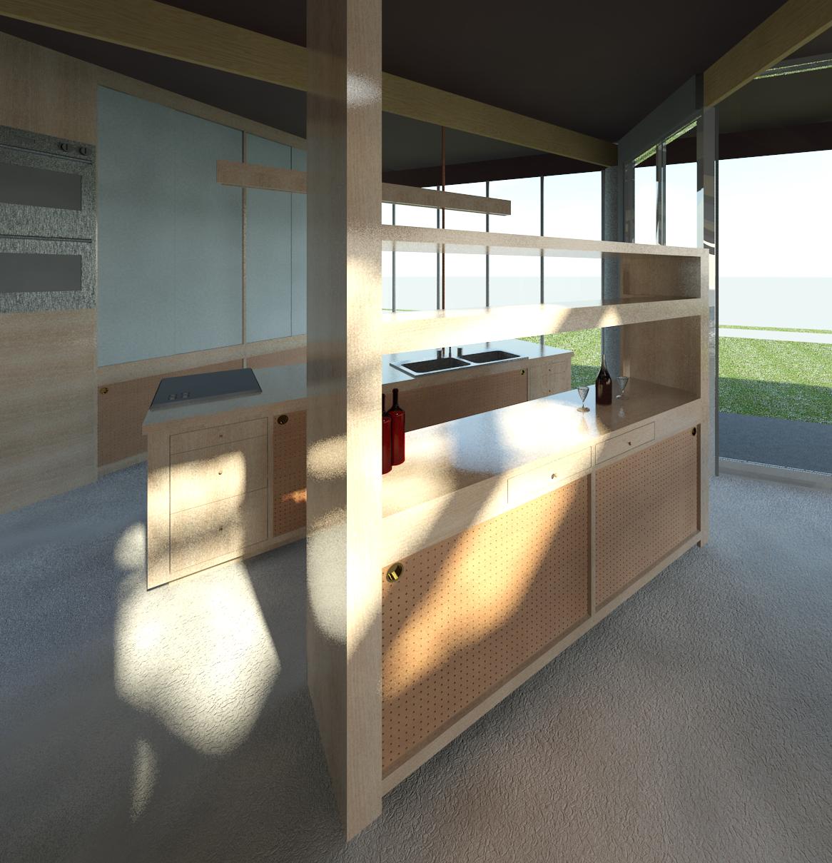
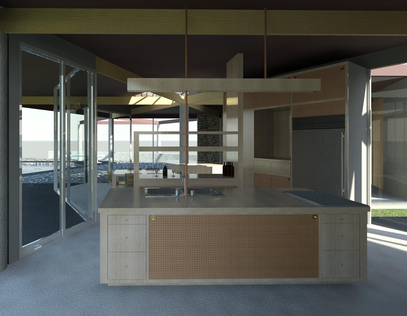
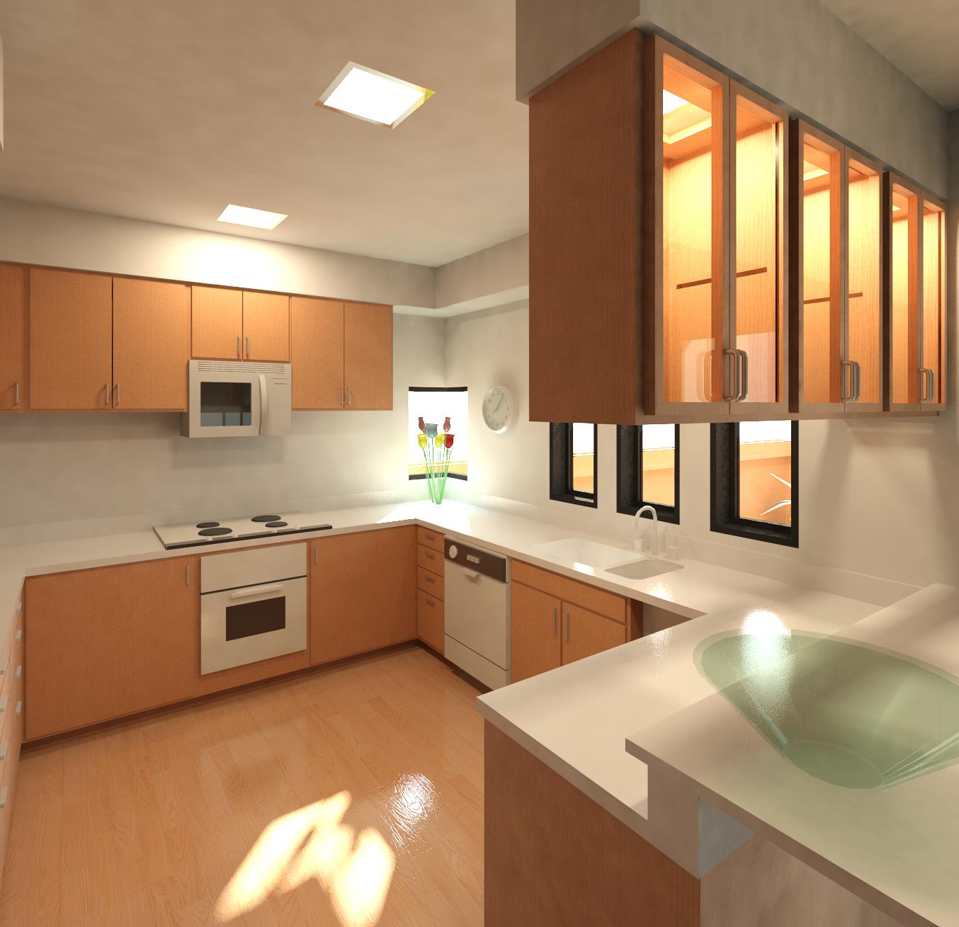
Kitchen to island
The kitchen island incorporates a cook top and sink. A contemporary induction cook top is currently modeled, but a period-correct gas cook top will eventually be modeled. The plans indicated that a laminated cutting board adjacent to the cooktop needs to be modeled.
The dimensions of the drawers and pegboard sliding doors are placeholders until access to the elevation drawings of the cabinetry depicting what was actually intended is granted.
The material used for the top of the island is modeled using oak, but access to the plans should reveal what was intended.
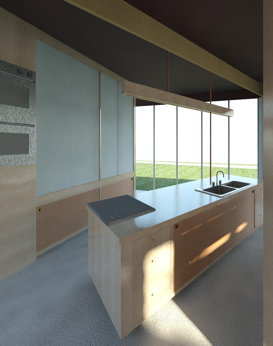
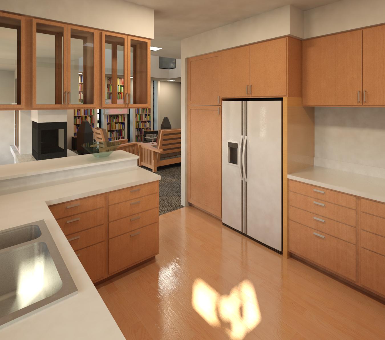
Kitchen to pool E
There is a note on the floor plan about a linear light fixture, electrical conduit, and a vent pipe over the kitchen island, but without access to the full set of plans, it is not known at what height over the island the light fixture was suspended from the roof structure above. The copper pipe to the North (left in this view) extends all the way down to the kitchen island counter top and acts as a vent for the sink plumbing.
Contemporary kitchen appliances such as the Sub-Zero refrigerator, double ovens, and induction cook top are depicted until such time as suitable images of period appliances are located to model.
The dimensions of the drawers and pegboard sliding doors are placeholders until access to the elevation drawings reveal what was actually intended.
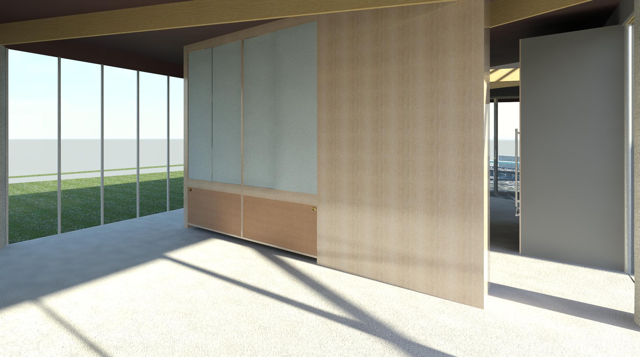
Kitchen to bedroom W
Without access to photos or the original elevations, it has proven difficult to remember the layout of the cabinets and shelves. The cabinetry depicted are place holders based upon what was remembered during the tour until the actual elevation drawings are made available so that accurate cabinetry details can be modeled.
Contemporary wall ovens are depicted until suitable period ovens are modeled.
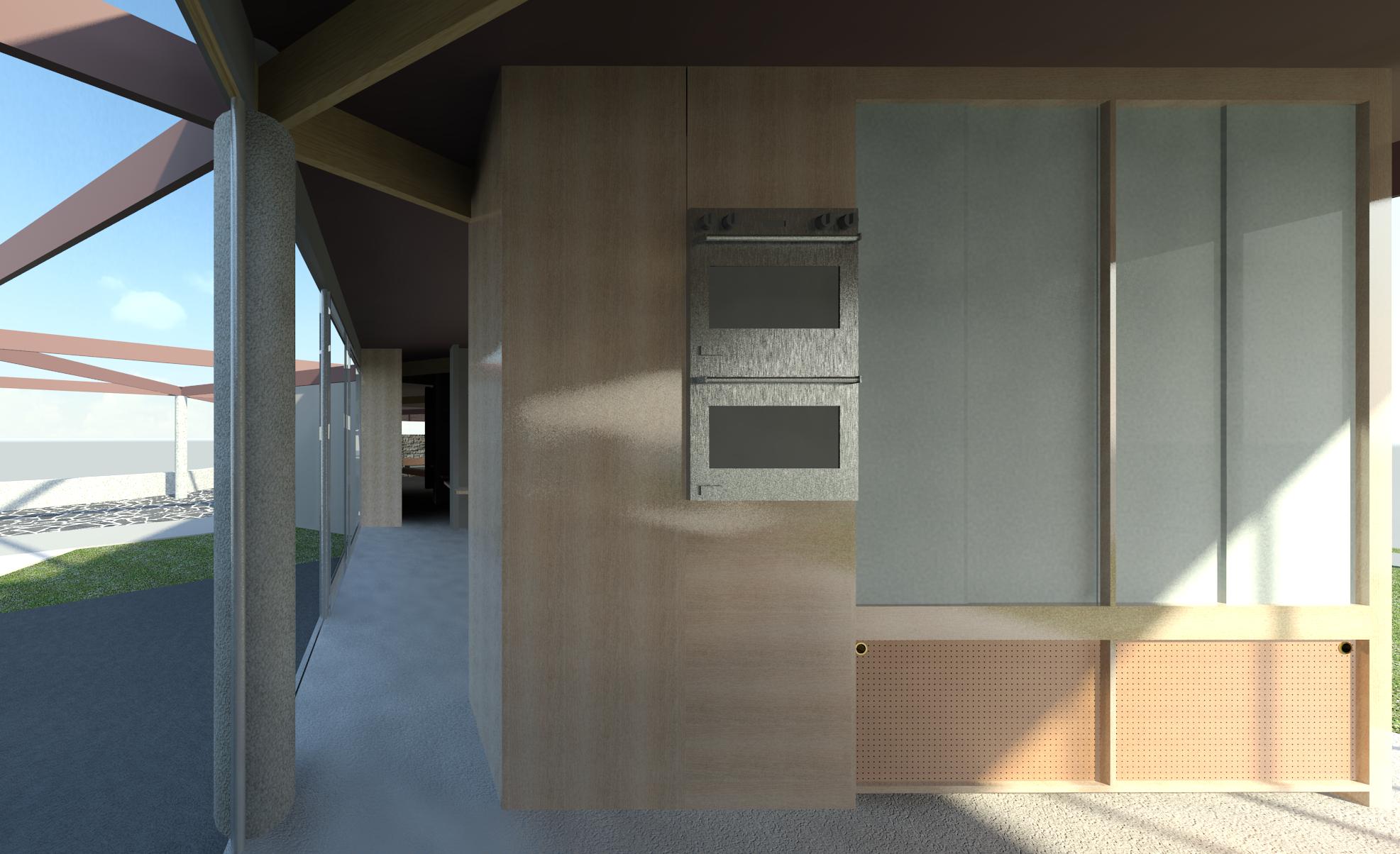
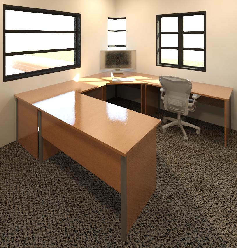
 Studio to NE
The East wall of the studio appeared blank without the cabinetry or exposed wood, but the floor plan indicates that the cabinetry mirrors that used on the other side of the wall in the kitchen. The back of the cabinets housing the ovens may have been plastered and painted gray instead of being exposed wood as depicted here. The elevation drawings may reveal what was actually intended.
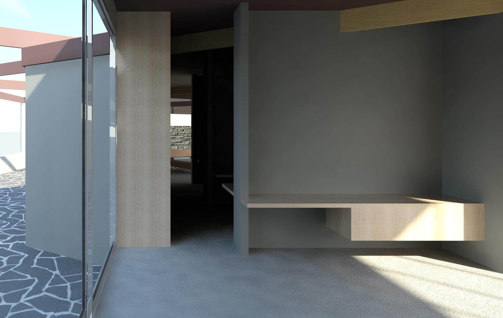
Studio to master bedroom W
Without access to photos or the original elevations, it has proven difficult to remember what the layout of the cabinets and shelves are. The cabinetry depicted are place holders until the original intent is known.
That hallway leading to the bathrooms and bedroom looks rather dark as only natural sunlight was used to generate the rendering, but artificial lighting will be added as time permits once the original lighting plan is known and the custom light fixtures are modeled.
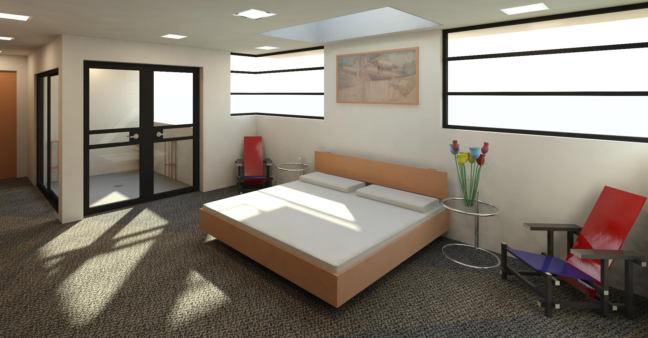
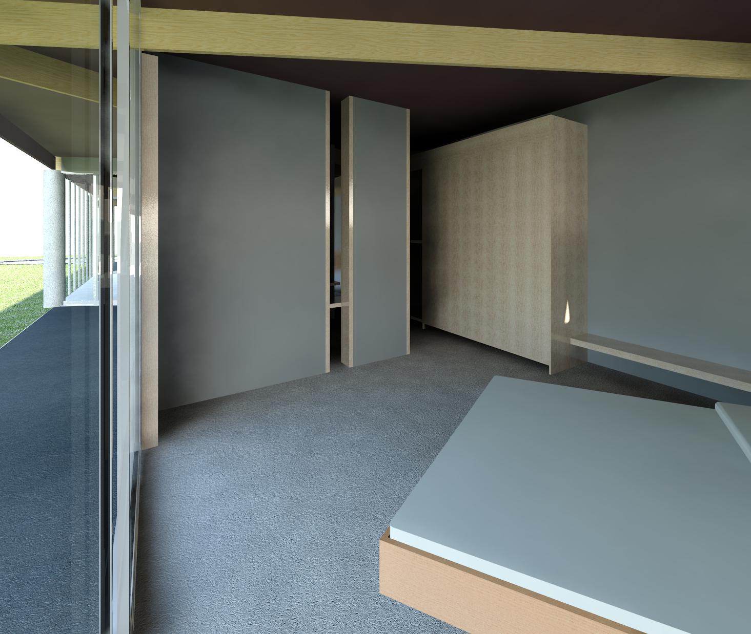 Master bedroom to SE
The closets in the master bedroom were specified on the floor plan with accordion-type folding wood doors that have yet to be modeled. Solid wood doors are currently depicted as seen during the tour.
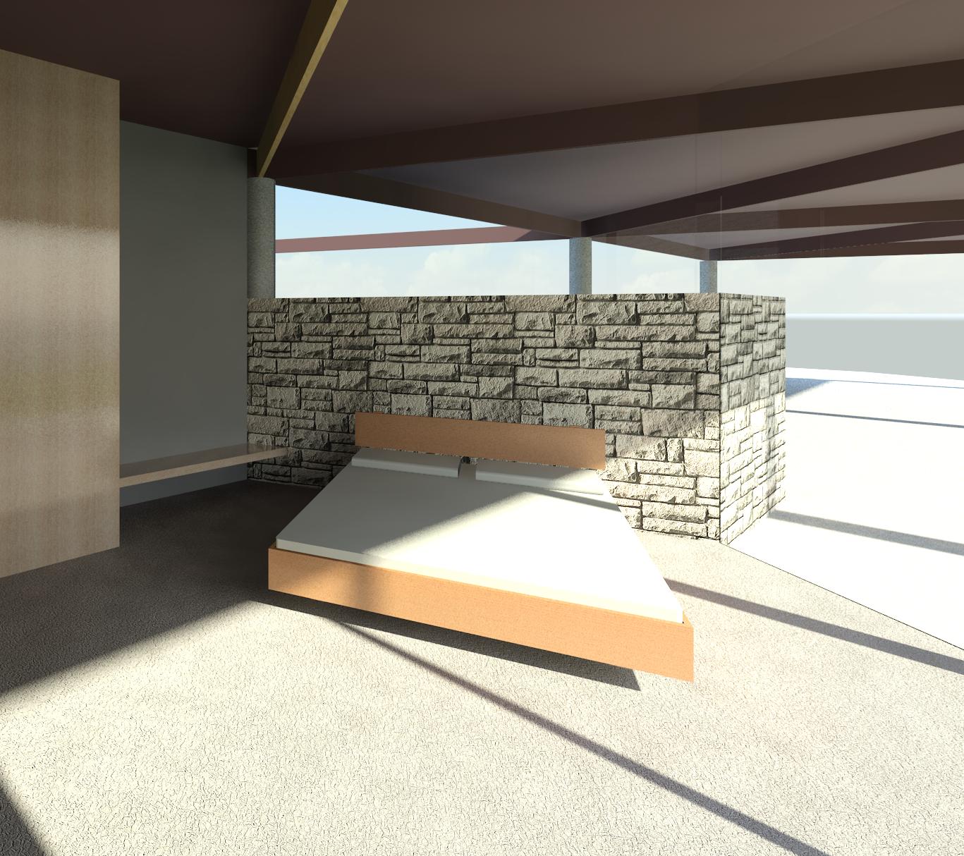
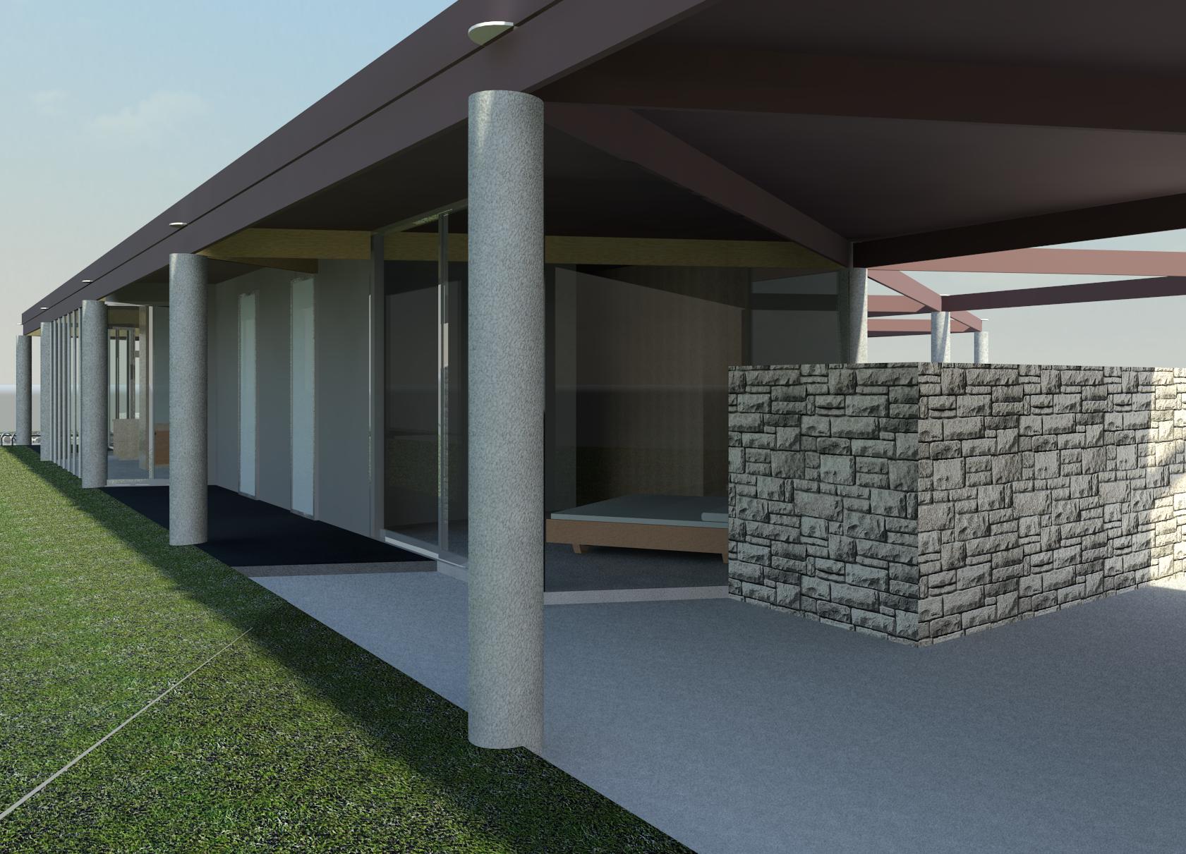
Master bedroom to carport SW
The closets in the master bedroom were specified on the floor plan with accordion-type folding wood doors that have yet to be modeled. Solid wood doors as seen on the tour are currently depicted.
The bedroom wall and fence were constructed using the same mostly off-white stone used around the fireplace. The type of stone used needs to be verified and then modeled. The height of the bedroom wall needs to be verified. Access to the plans or a visit to the site will reveal what was intended and ultimately built.
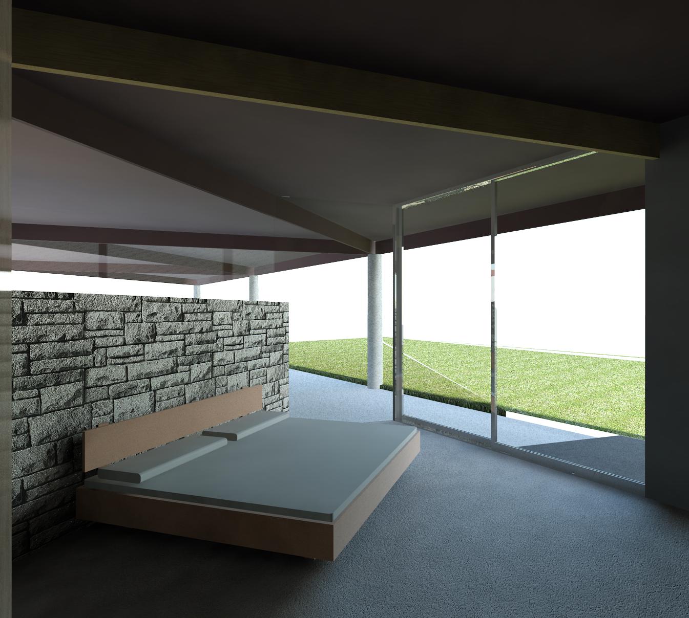 Master bedroom to lawn NW
No bed size was depicted in the floor plan so a king size bed was modeled.
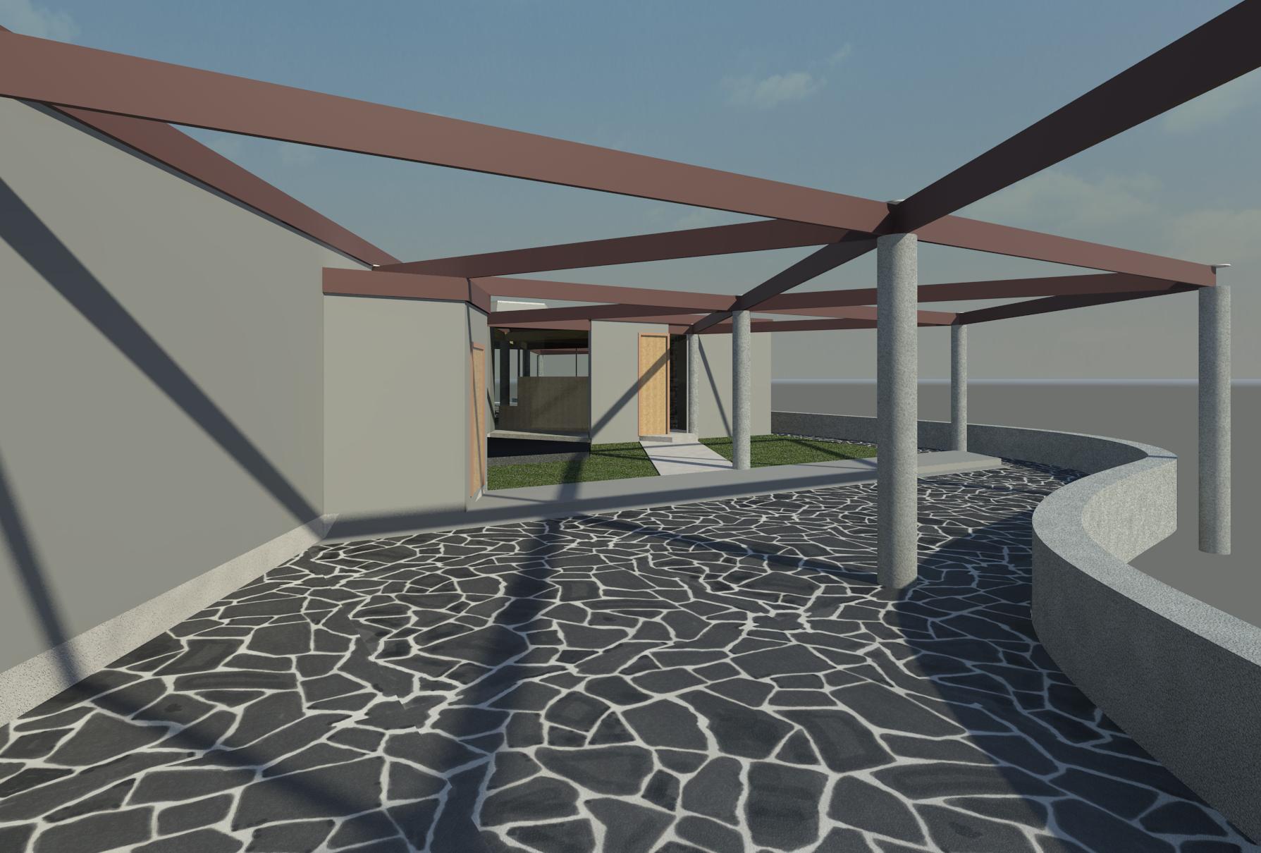
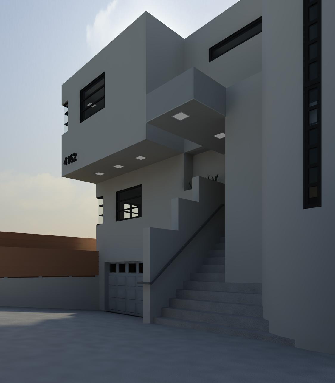
Courtyard to the front door E
The continuation of the columns and beams beyond the roof perimeter create a trellis-like space above the entry courtyard which is evident in period photos where the beams are covered in greenery.
There is a steep hillside South (right in this view) beyond the short retaining wall. Modeling a complete site topography awaits access to the original site plan.
There were planters along the South (left in this view) walls of the house but they were not depicted on the floor plan. Access to the original plans will show if the planters were a part of the initial design.
The west end of the courtyard is mostly concrete not black slate as currently depicted. The flooring material will be updated.
Courtyard to W
The multiple floor levels in the entry courtyard were constructed using the same off-white stone used around the fireplace as well as natural gray concrete and black concrete. The type of stone used will be verified and then modeled.
The material for the gates is depicted as wood but the type of material and design of the gate is not known until the original plans can be accessed.
The west end of the courtyard floor near the gate is concrete not black slate as currently depicted. The flooring material will be updated.
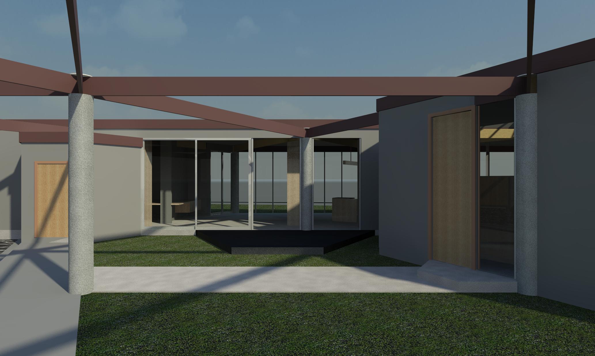 Courtyard to house N
The multiple floor levels in the entry courtyard were constructed using the same off-white stone used around the fireplace and natural gray as well as black concrete. The concrete slab just outside of the kitchen and studio areas is tinted black.
Lawn to bedroom SE
The two sliding aluminum doors with frosted glass provide access to the lawn from the two bathrooms.
The exterior concrete on the North side of the house is tinted black.
The bedroom wall and fence were constructed using the same mostly off-white stone used around the fireplace. The type of stone used needs to be verified and then modeled.
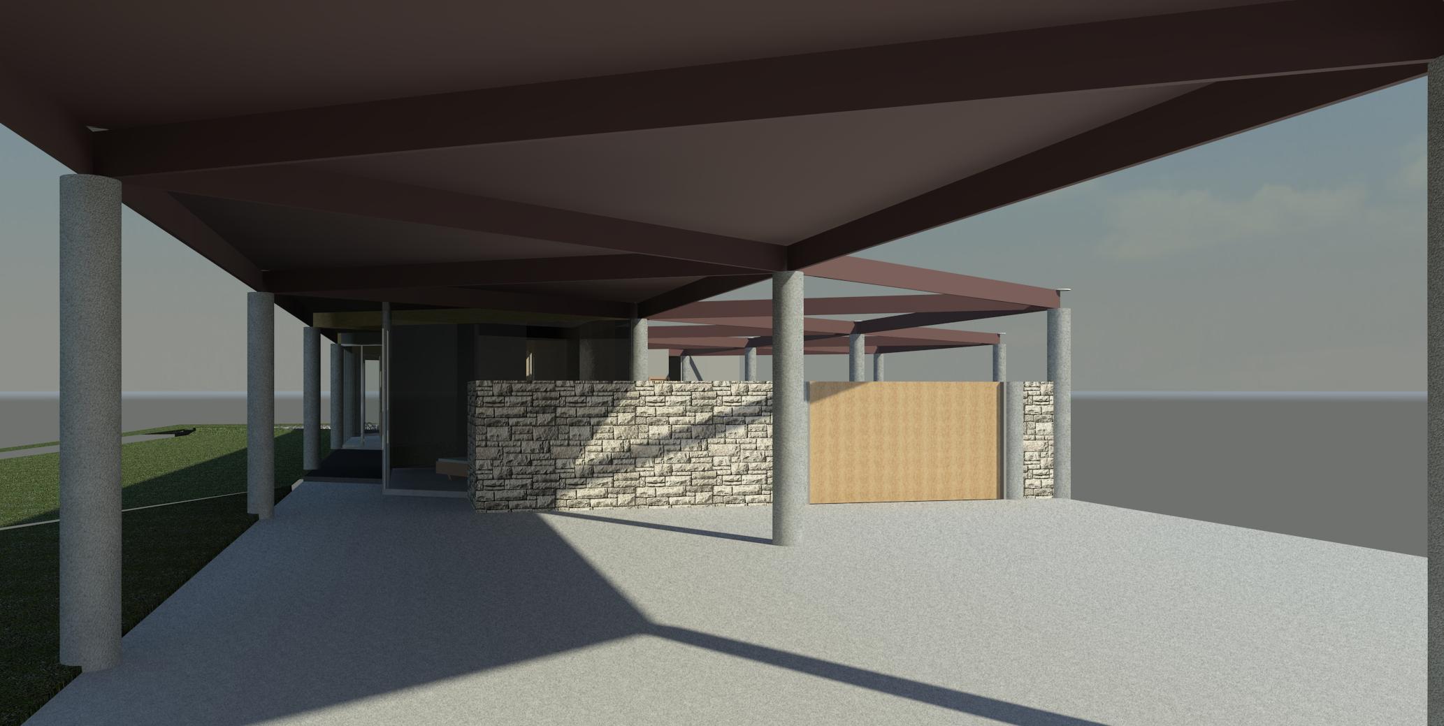
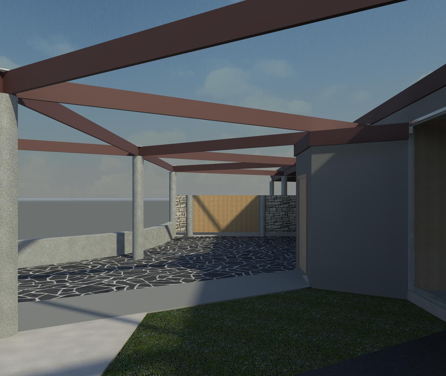
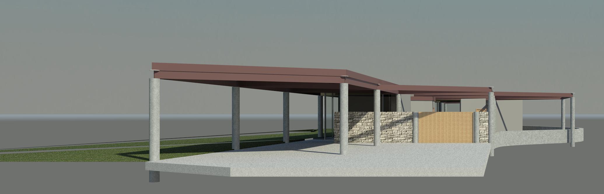
Carport to house E
A fence and gate are depicted per the floor plan, but the height of the fence and gate may be off. Access to the elevations in the full set of plans should reveal what was intended.
The fence used the same mostly off-white stone that was used around the fireplace. The type of stone used needs to be verified and then modeled. The material for the gates is depicted as wood but the type of material and design of the gate is not known until the original plans can be accessed.
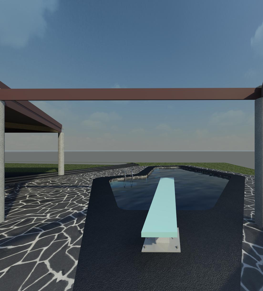 Swimming pool to N
The swimming pool walls need to be plastered and three entry/egress steps added to the North-West corner of the pool. The swimming pool pump and filter also need to be modeled. There is a planter area adjacent to the pool that needs to be modeled.
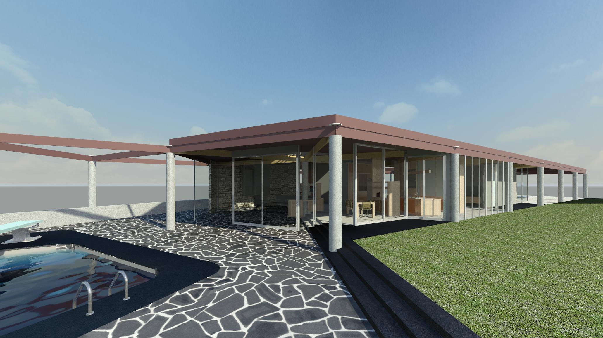
Pool to patio SW
There is a steep hillside South (left in this view) beyond the short retaining wall. Modeling a complete site topography awaits access to the original site plan.
The concrete steps from the lawn down to the pool area as well as the exterior concrete on the North side of the house and the pool coping are tinted black.
There is a planter area adjacent to the pool that needs to be modeled.
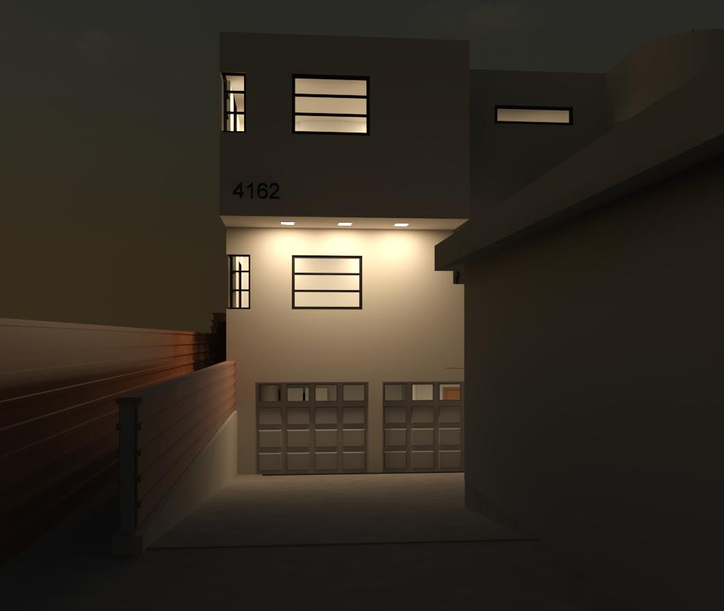
 Driveway to house E
There is a steep hillside South (right in this view) beyond the short retaining wall. Modeling a complete site topography including the hillside and driveway awaits access to the original site plan.
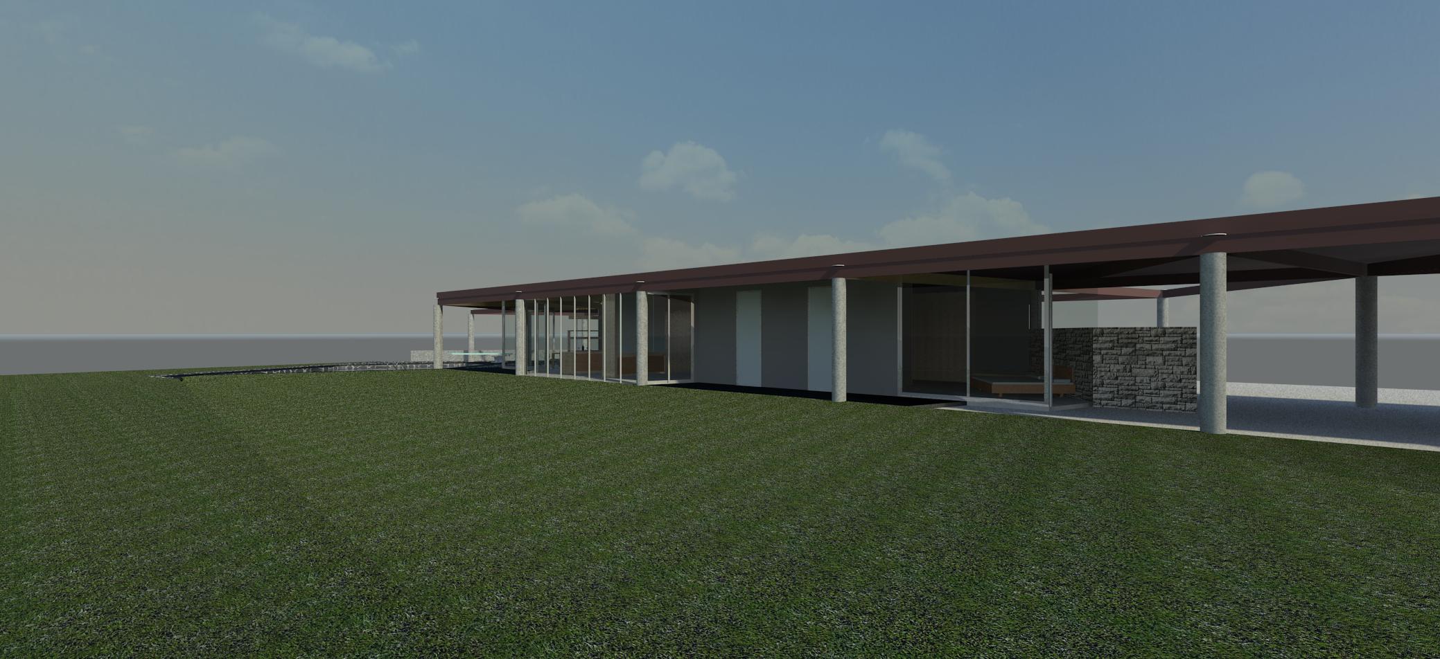 Lawn to house SE
The two sliding aluminum doors with frosted glass provide access to the lawn from the two bathrooms.
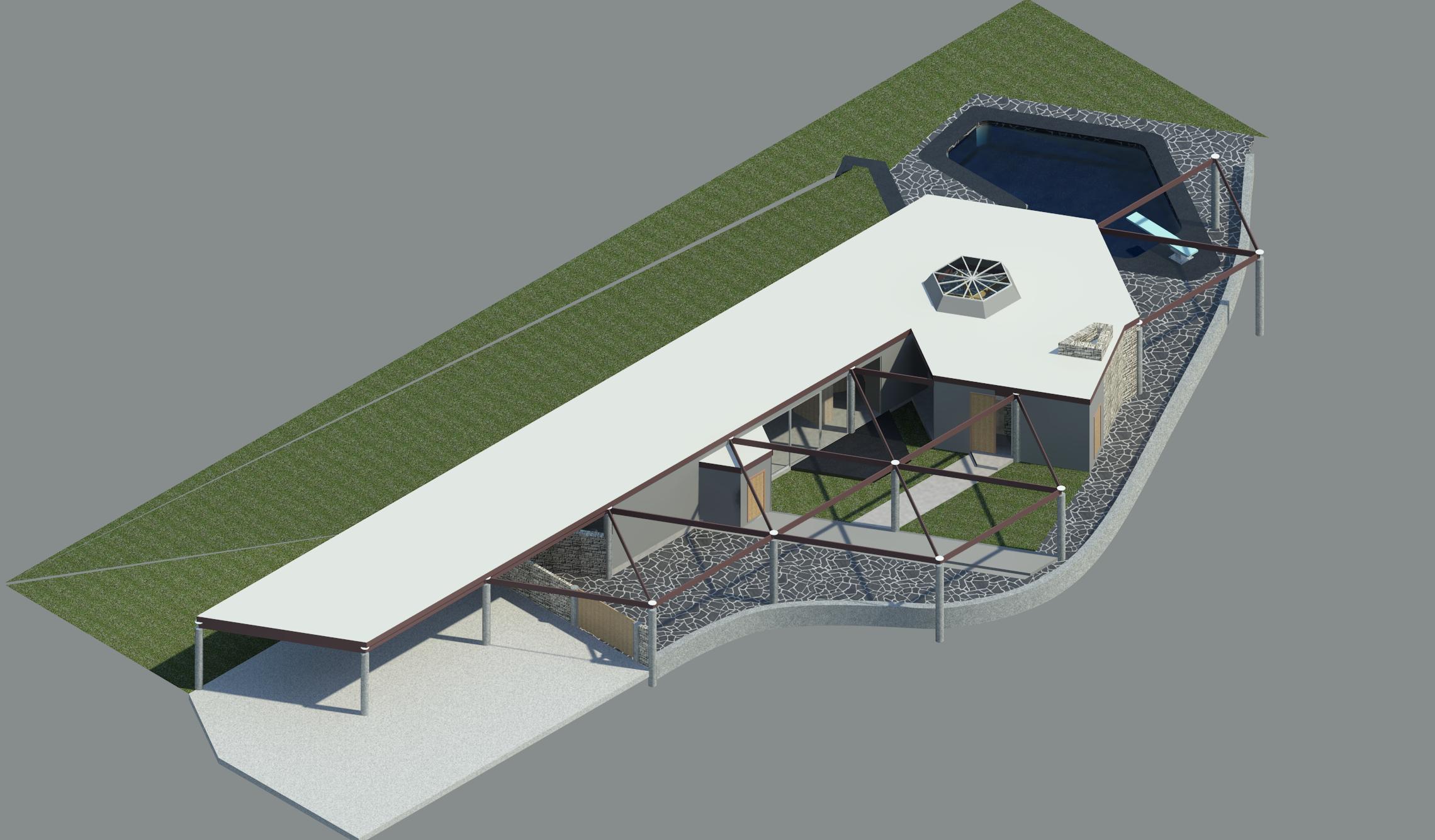
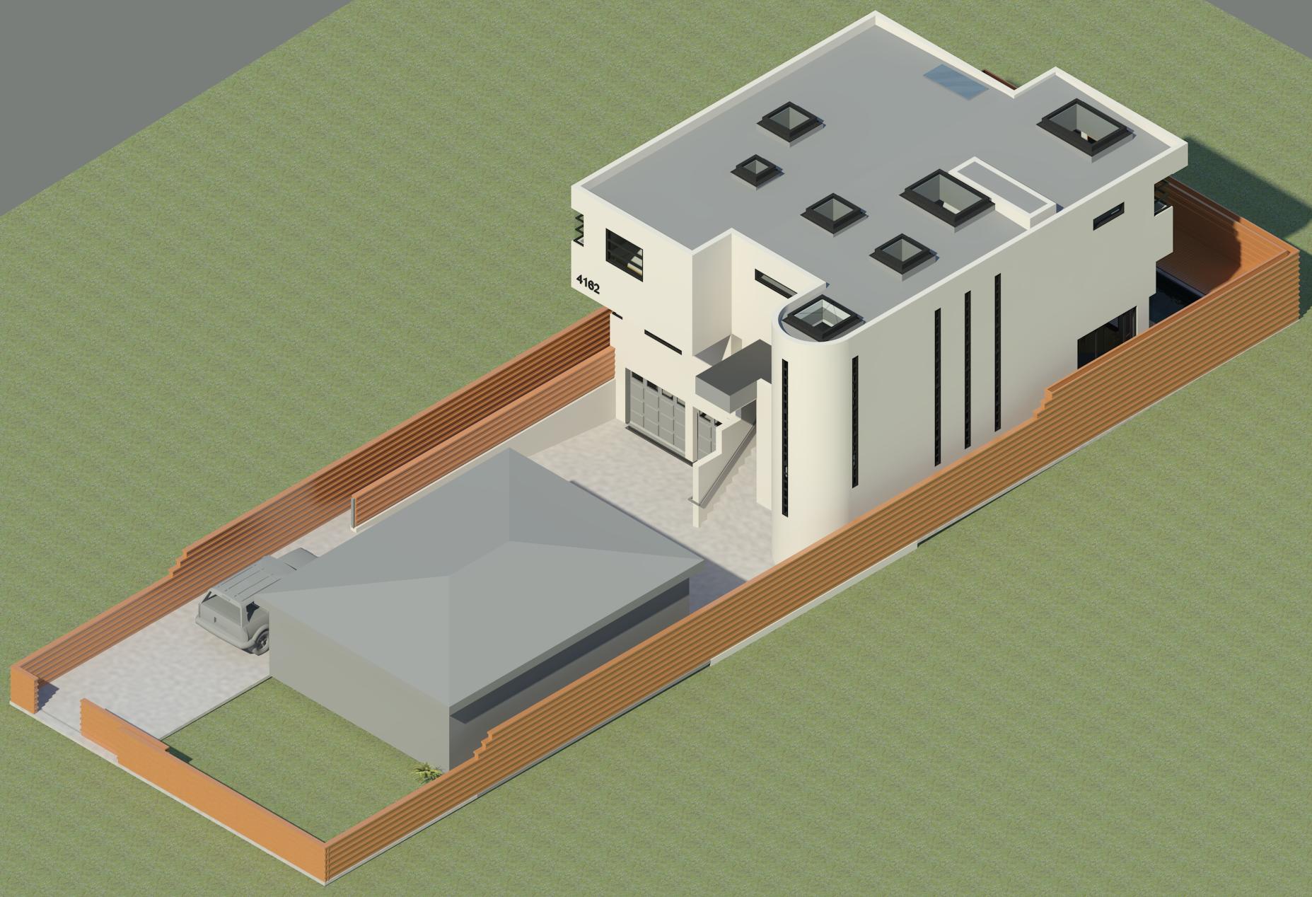
Aerial view to NE
When the model is complete with accurate topography, high resolution aerial renderings will be generated and depicted here.
The multiple floor levels in the entry courtyard were constructed using the same mostly off-white stone used around the fireplace along with gray and black concrete. The type of stone used needs to be verified and then modeled.
The west end of the courtyard floor near the gate is concrete not black slate as currently depicted. The flooring material will be updated.
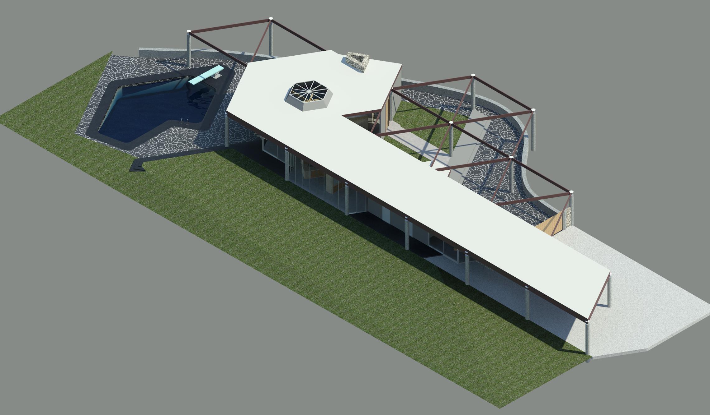
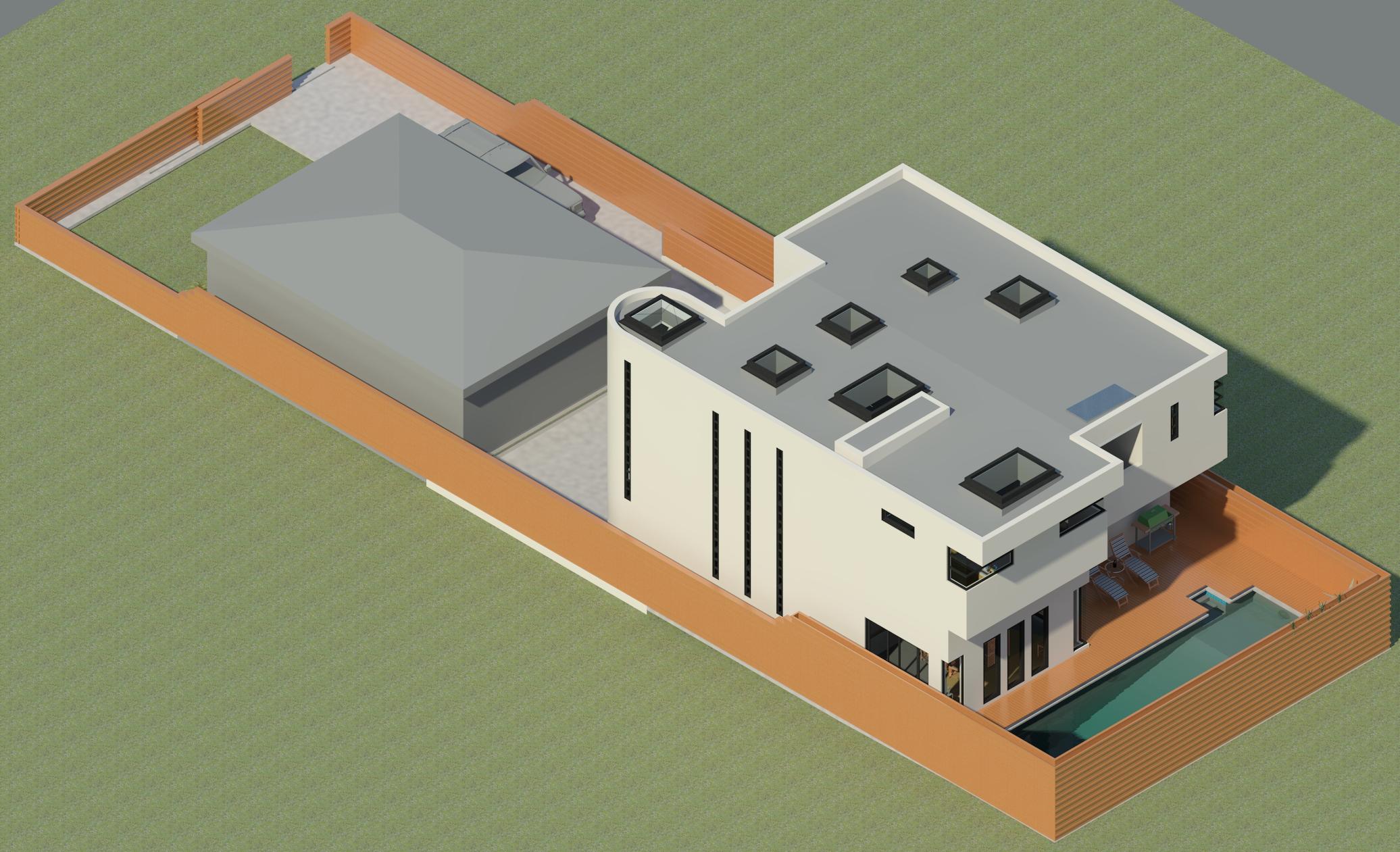
Aerial view to NW
The configuration of the fireplace chimney above the roof level is not known. Access to the plans or a visit to the site will reveal what was intended and ultimately built.
The west end of the courtyard floor near the gate is concrete not black slate as currently depicted. The flooring material will be updated.
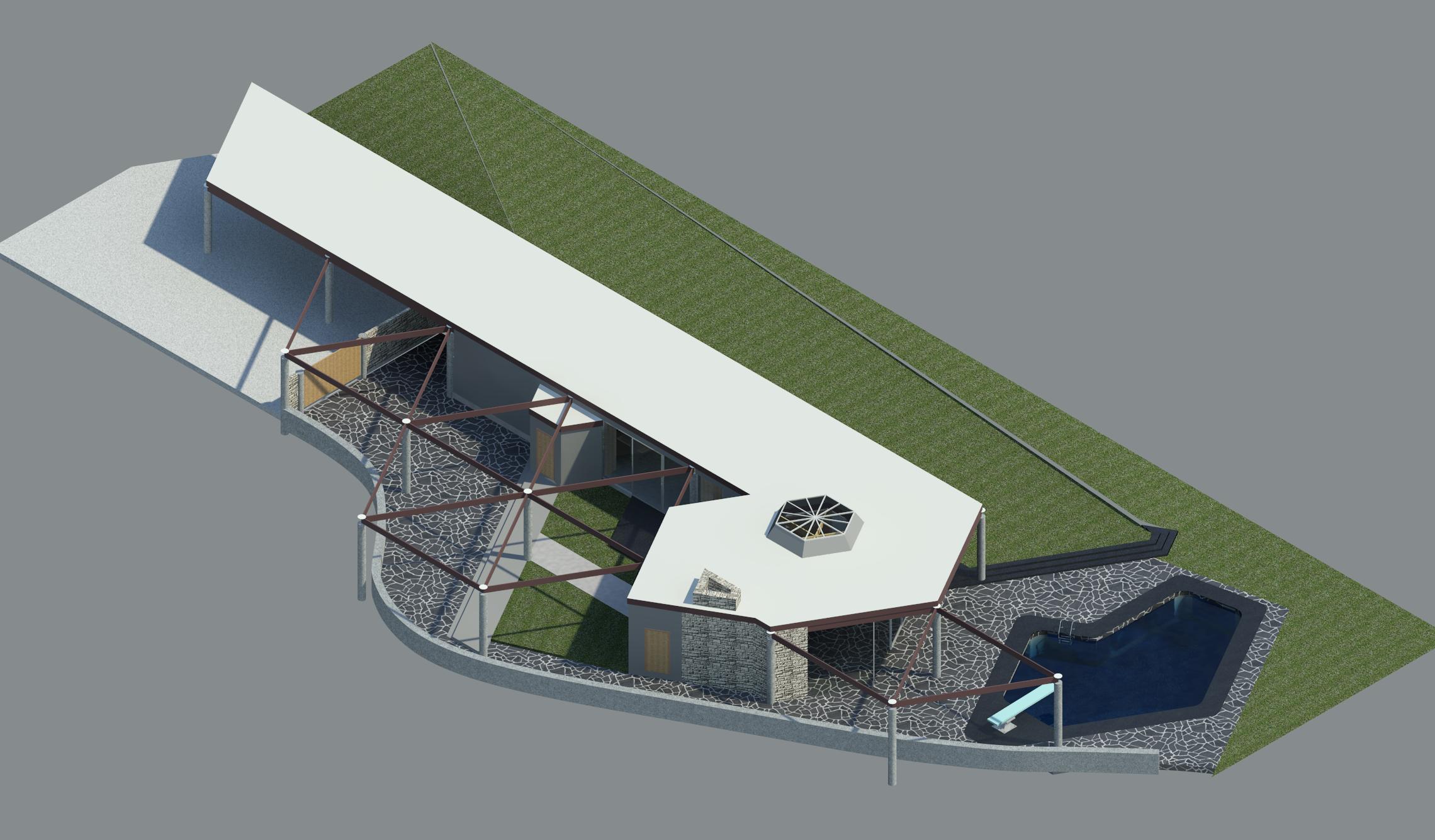
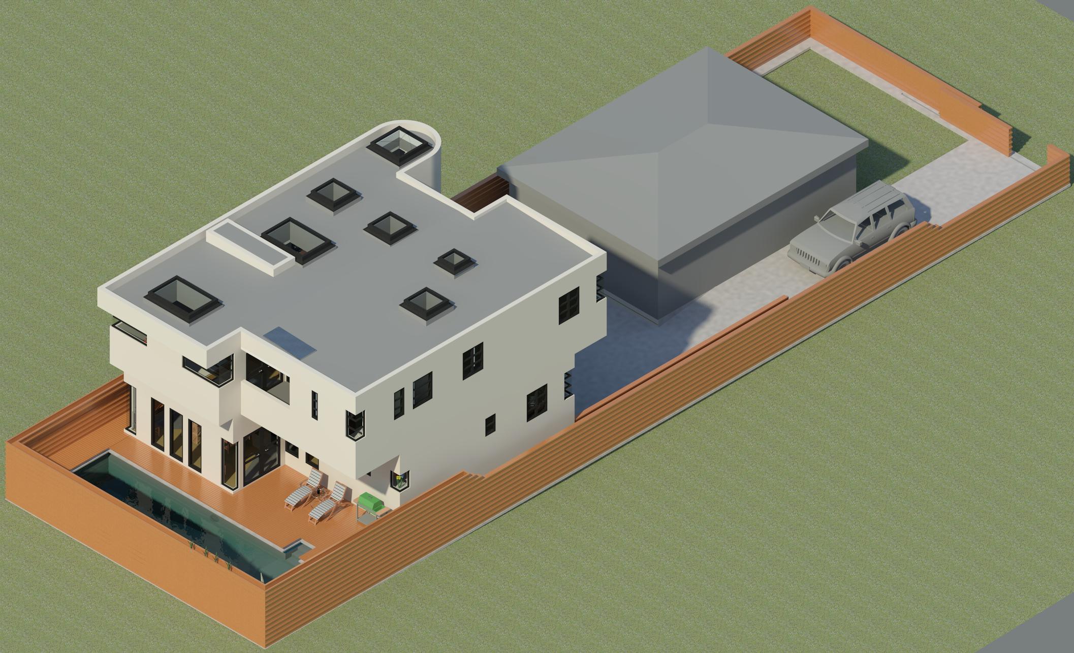
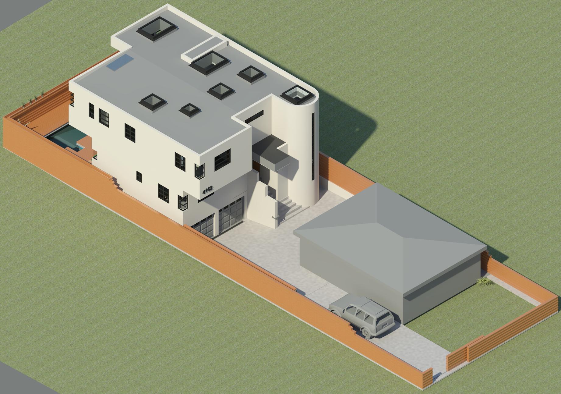
 Aerial view to SE
The west end of the courtyard floor near the gate is concrete not black slate as currently depicted. The flooring material will be updated.
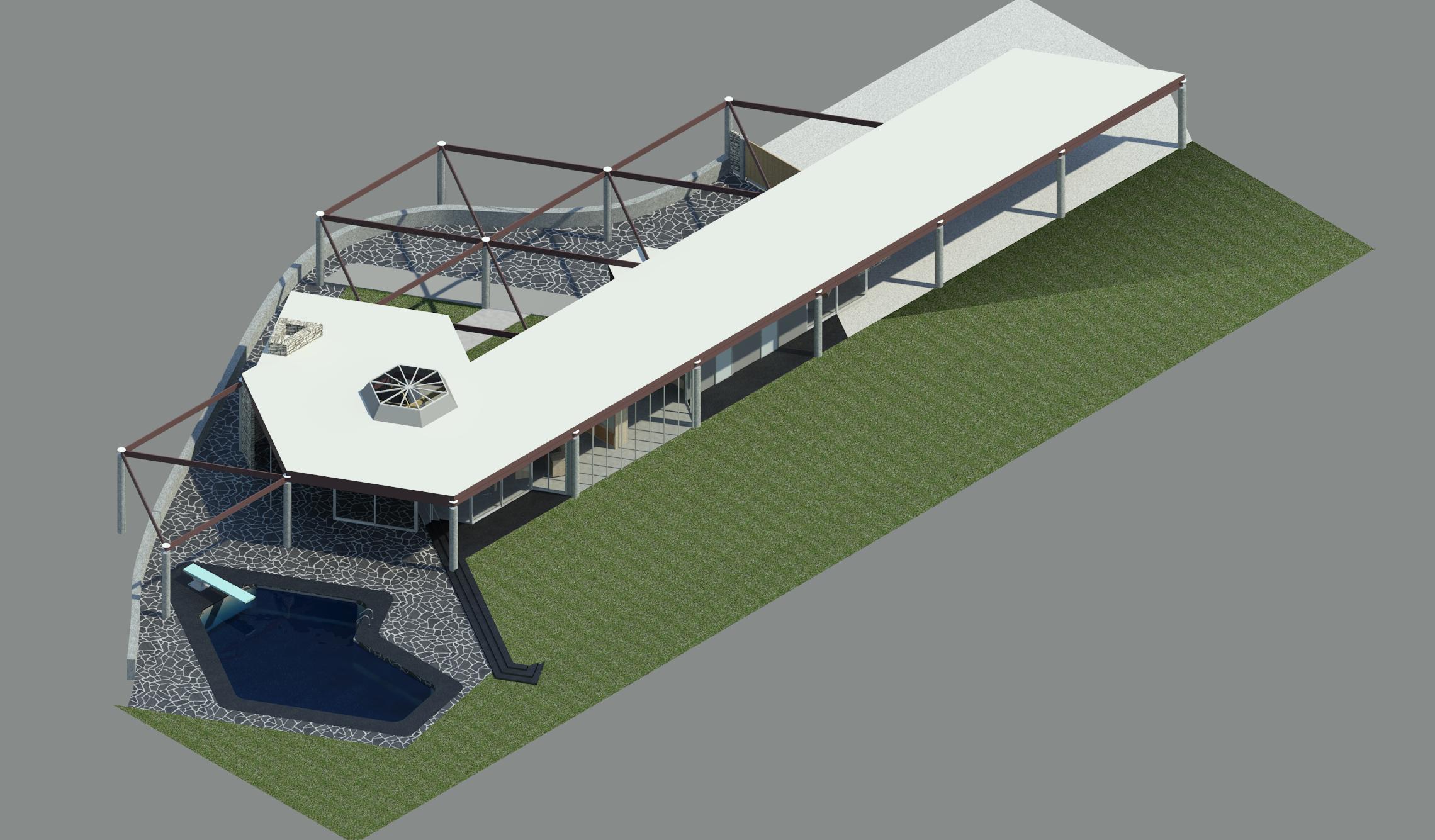
Aerial view to SW
The exterior concrete on the North side of the house as well as the steps from the lawn down to the pool area and the pool coping are tinted black.
The west end of the courtyard floor near the gate is concrete not black slate as currently depicted. The flooring material will be updated.
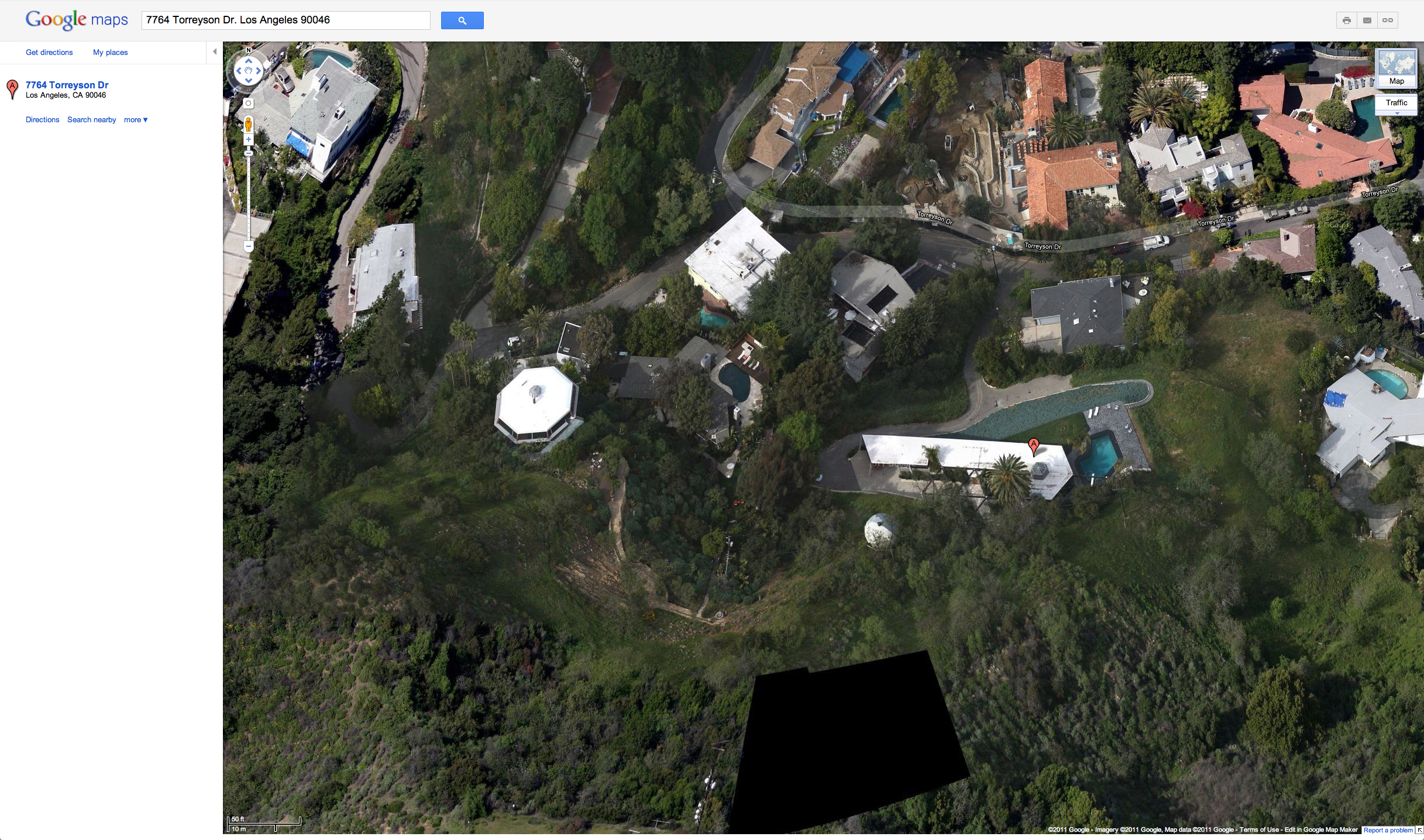
The Harpel and Chemosphere houses
This image from Google Maps shows not only Mr. Lautner's Harple house just right of center (marked with "A"), but also Mr. Lautner's famous octagon-shaped Chemosphere house for Mr. Malin at the top of the hill to the left of center. North is up.
Mr. Malin saw the Harpel house under construction and commissioned Mr. Lautner to design a house for his very difficult hilltop site. The rest is history.
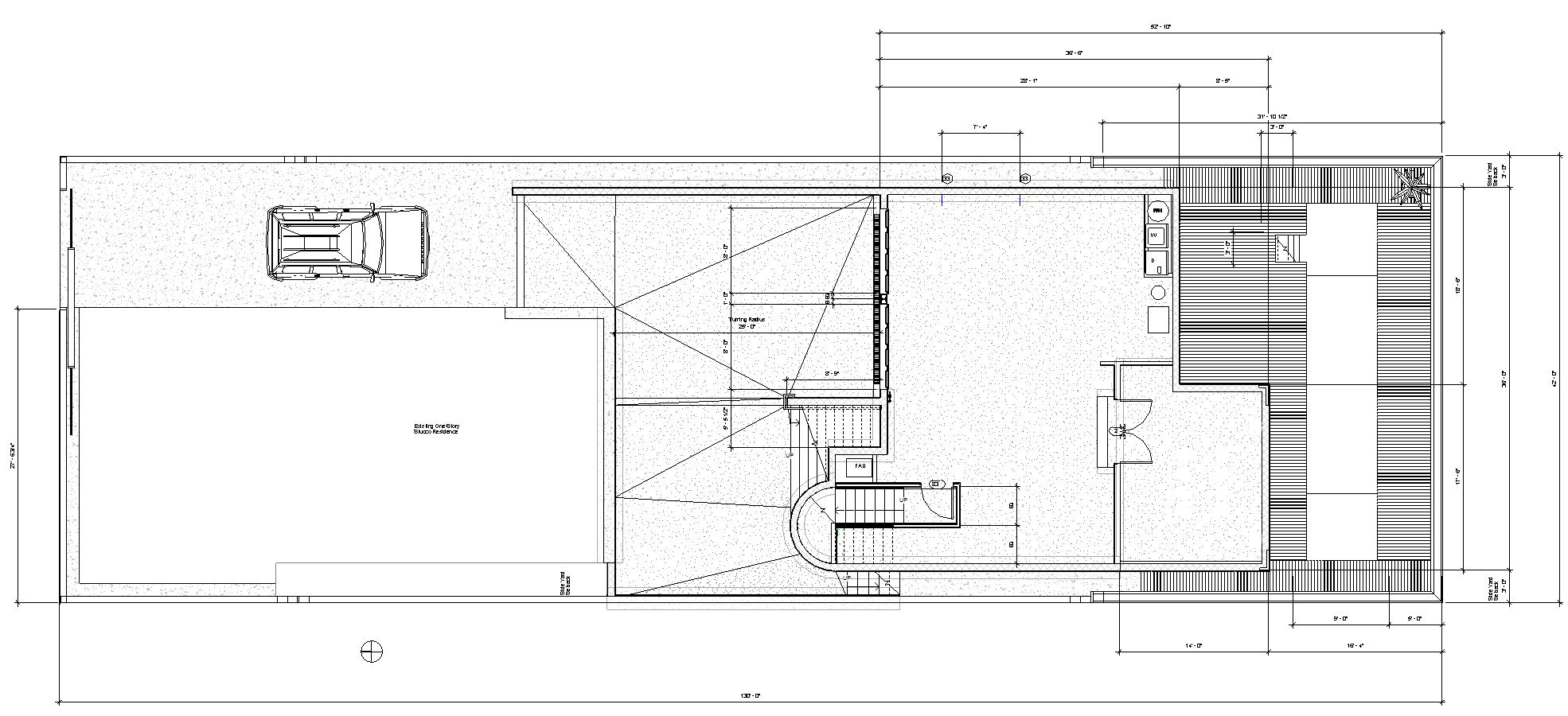
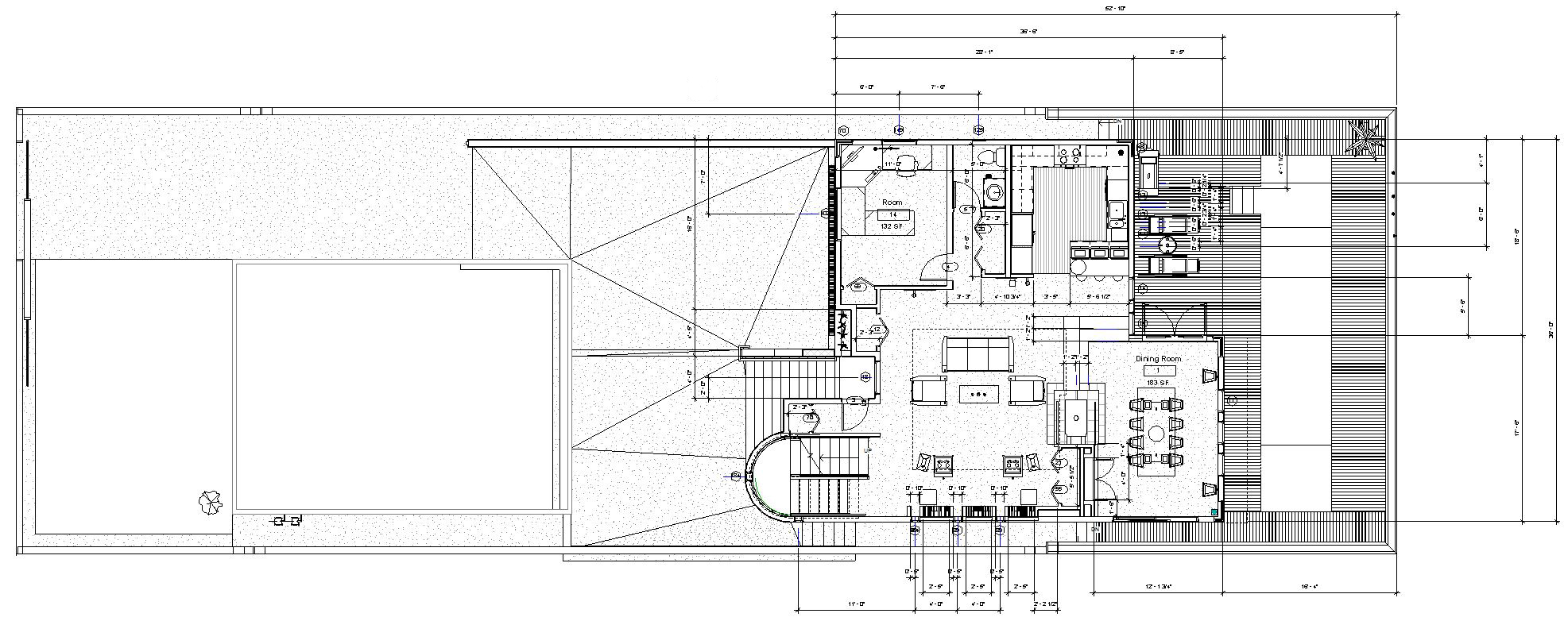
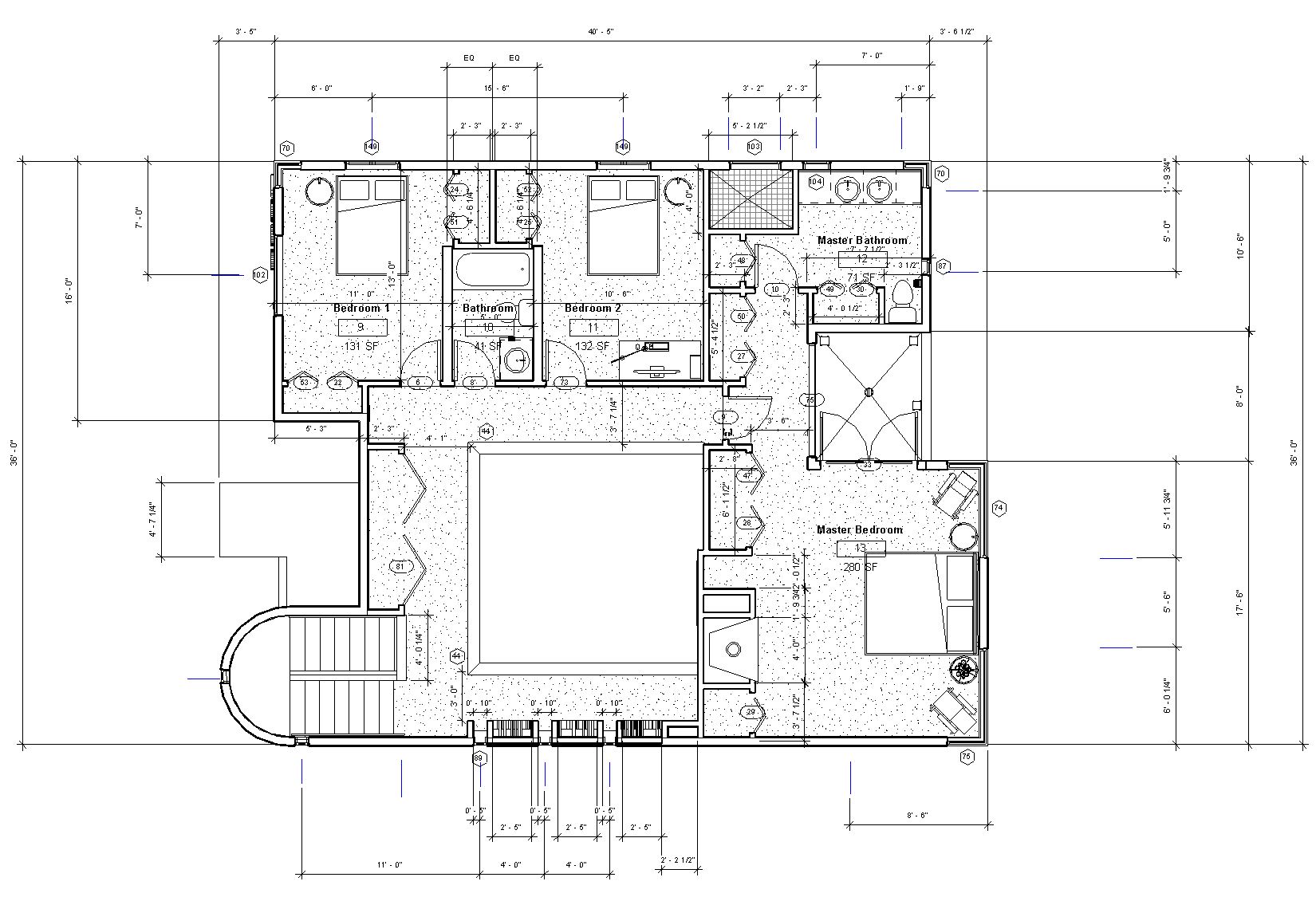
 Floor plan
This is my interpretation of the original floor plan. North is up. There is an additional existing guest bedroom West of the master bedroom under the carport roof structure, but since it is not depicted in the original drawings, it was not modeled.
John Lautner's 1956 Harpel house I renderings overview
We toured Mr. Lautner's 1956 Harpel house I on July 23, 2011 during the MAK Center and John Lautner Foundation sponsored "Lautner Birthday Tour" celebrating Mr. Lautner's 100th birthday. That tour was the inspiration for creating a Revit model of the Harpel house. Unfortunately, interior photography was not allowed so the only resources for constructing the model were a tiny reproduction of the floor plan and four period photographs published in the monograph "John Lautner Architect" by Frank Escher.
There is an unexecuted 1956 design by John Lautner for Mr. Harpel that is more circular in plan. It is not known by me if the unexecuted design was submitted to Mr. Harpel before the design that was built or if the unexecuted plan was proposed after the design that was actually built. Access to the dates on the plans at the Getty Research Institute should clear up any confusion when the entire catalog is made available in 2012. Therefore, what I refer to as the first Harpel House may in fact be the second design which would also make the house in Alaska actually the third design for Mr. Harpel.
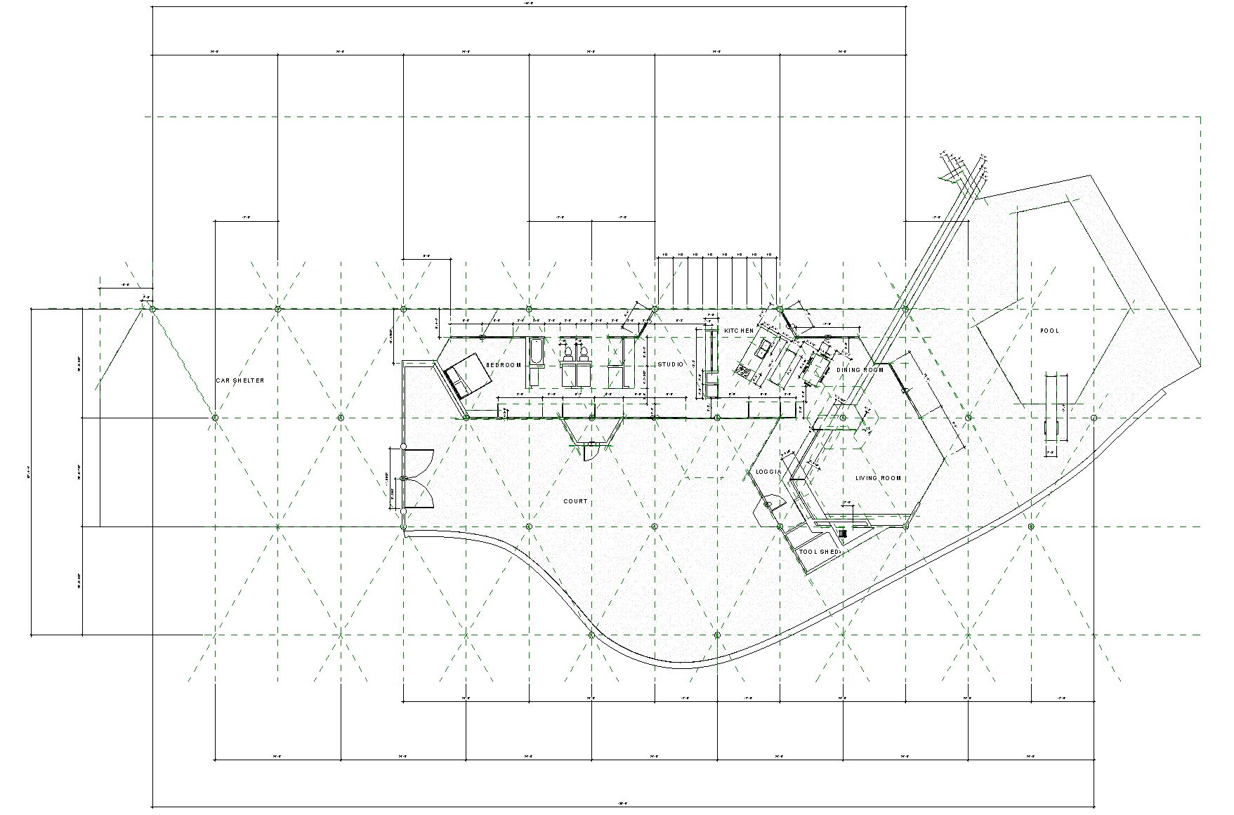
The building site, on a steep hillside in the Hollywood Hills with a great view of the San Fernando Valley, is largely composed of fill. In response to the poor soil conditions, Mr. Lautner used concrete caissons set on a 24'-0" hexagonal grid upon which the roof is set with a concrete slab floor below. The continuation of the columns and beams outside the house generate a trellis-like space in the entry courtyard.
The public spaces consist of the living room, dining room, and kitchen areas inside the "head", with a patio, swimming pool, entry courtyard, and carport outside. The private spaces forming a "tail", consist of a studio, two bathrooms, and a master bedroom. This head and tail approach was used by Mr. Frank Lloyd Wright for many of his Usonian home designs. Mr. Lautner was an apprentice at Mr. Wright's Taliesin School.
Mr. Harpel (a radio announcer) performed labor and acted as the general contractor alongside a master builder after office hours. Mr. Harpel later engaged Mr. Lautner to design another house for him in 1966 (Harpel house II) for Anchorage Alaska using carved and painted totem poles as supports.
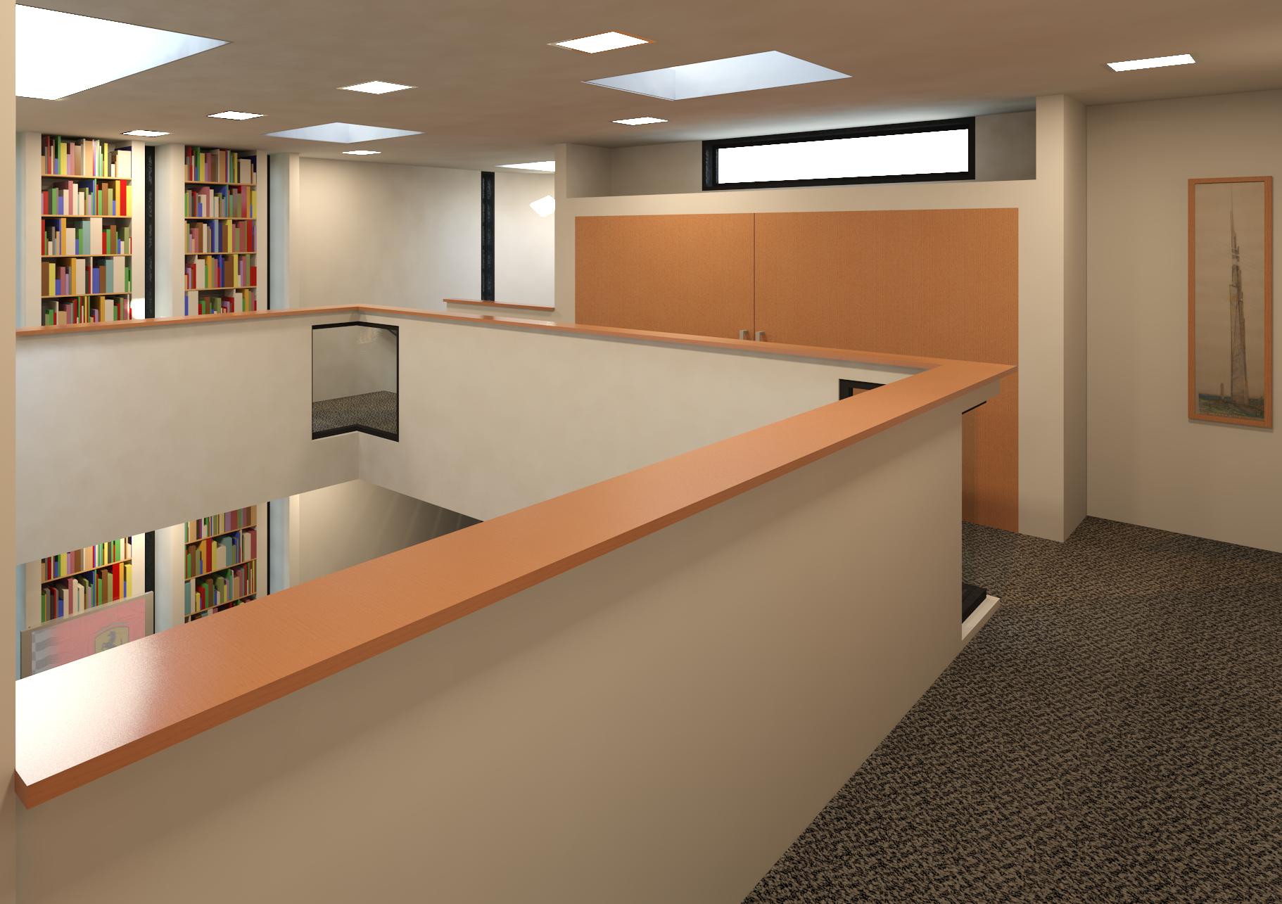
Subsequent owners added a partial second floor with a library to the Harpel house with seemingly little regard to Mr. Lautner's design intent. Thankfully, the current owner removed the second story spaces during a recently completed extensive restoration. This model represents the house as depicted in the original floor plan. Features such as the wall and gate enclosing the entry courtyard which are depicted in the original floor plan but not in evidence today are included. The existing guest bedroom West of the master bedroom under the carport roof that is not depicted on the original plans was not modeled.
Most of the dimensions were guessed at because the tiny reproduction of the floor plan in Mr. Escher's monograph lacked sufficient detail to discern all of the dimensions. Since no elevations were available to go by, much is guesswork gleaned from what was vaguely remembered during the 15 minutes we were at the site during the tour. All errors in the model are mine alone.
"You can do nothing to improve your life more than by living in great architecture" - John Lautner
Work on the model still to be completed:
- Update the cabinetry design and materials to reflect actual intent
- Create
the bathroom sinks and built-in cabinetry in the bathrooms
- Create a site plan and model the site topography
- Create a lighting plan, model the custom light fixtures, and then generate a few night renderings
- Model the roof structure
- Clean up the swimming pool model geometry
- Generate a custom mostly off white stone material for the fireplace and entry courtyard
- Perform miscellaneous cleanup of the model geometry and materials
- Generate an animated video walk-through of the model.